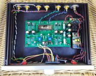
So, this is my final wiring of the Academy Audio Volume Control Unit into the Korg preamp. I got lots of help and information along the way from Lenny at Academy Audio, he was a great help in clearing up my uncertainties about the volume control setup.
The control works exactly as it should and it sounds really good -- essentially transparent, and I love the IR remote capability. Highly recommended.
A bit of humour -- I mildly complained to Lenny about the crossed signal wires from the volume control to the pcb, and his reply was that if I hadn't installed his control upside-down it would be right!
Attachments
Last edited:
One last thing about the AA volume control -- I notice that the way I installed it, the bottom edge of the volume pcb is right at the bottom plate of the Korg chassis. I would say it fits comfortably but without room for error. Just be careful.
Make the LED resistor 15K-20K.
You were dead on -- perfect at 22.1K.
Hi Wapo
Glad you enjoy it!
I understand the Muses shouldn't be too sensitive to PS, but just in case of, if you have a spare SMPS filter you could try to fit it in front of the Muses board...
Just thinking out loud
Enjoy music
Claude
The guys on another thread have just created a filter that seems ideal for use with the AA VCU and an SMPS power splitter:
https://www.diyaudio.com/forums/analog-line-level/354213-po89zb-inline-dc-filter-smps-wall-warts-preamps-hpa-korg-nutube-etc-new-post.html
For those thinking of using the Academy Audio, Muses volume control AA is offering a bundle deal with the Volume control, remote, display and +/-14 volt power supply at $159.99.
VCU+LPS9 Bundle, Hi-End MUSES(R) Micro Volume Control Board + Low Noise Power | academyaudio
VCU+LPS9 Bundle, Hi-End MUSES(R) Micro Volume Control Board + Low Noise Power | academyaudio
I have been thinking about my just-finished Korg with AA VCU project and I want to add some features.
The three features I'm thinking about are:
1. Back panel relay switched inputs with control from the front panel toggle.
2. Back panel output relay with 3-second delayed connect and instant disconnect when power is lost or turned off.
3. Power amp trigger output -- 12vdc & 25(?)mA.
Question I have relates to the trigger voltage ground. Does it have to be a floating ground referenced only to the power amp, or can it be directly connected to the Korg ground which would mean the Korg and the power amp would share a ground? I can't seem to find a trigger circuit that addresses much detail like that.
Does anyone have a schematic of a commercial trigger supply in a commercial preamp that would answer the question?
Easy B1KORG Ajustment mod
Hi,
I'm considering adding a small voltage meter on the front panel to show the R7 & R8 voltages. Moving the 10KR trim pots to the front panel.
This way the voltages can be adjusted easily to quickly change the 2nd to 3rd harmonic distortions.
Any comments or sugestions?
ICHIs
Hi,
I'm considering adding a small voltage meter on the front panel to show the R7 & R8 voltages. Moving the 10KR trim pots to the front panel.
This way the voltages can be adjusted easily to quickly change the 2nd to 3rd harmonic distortions.
Any comments or sugestions?
ICHIs
Hi,
I'm considering adding a small voltage meter on the front panel to show the R7 & R8 voltages. Moving the 10KR trim pots to the front panel.
This way the voltages can be adjusted easily to quickly change the 2nd to 3rd harmonic distortions.
ICHIs
Don't do it. I found that the plate voltage continues to drift lower as the tube aged. I have the unit for a little over 3 months, and I've adjusted the voltage twice when I was changing out some parts (vol pot, etc). At the second adjustment, I saw the voltage drifted down to 8.86v. I adjusted it back to 9.5v and the sound was not right. It was dry and clinical. I ended up putting it back to 8.86v and the sound was glorious again.
Don't do it. I found that the plate voltage continues to drift lower as the tube aged.
Good to know, thanks. With voltage meters on the face plate I would see this occurring and make a note of it.
 A meter on the panel is always cool.
Don't do it. I found that the plate voltage continues to drift lower as the tube aged. I have the unit for a little over 3 months, and I've adjusted the voltage twice when I was changing out some parts (vol pot, etc). At the second adjustment, I saw the voltage drifted down to 8.86v. I adjusted it back to 9.5v and the sound was not right. It was dry and clinical. I ended up putting it back to 8.86v and the sound was glorious again.
Hearing this kinda troubles me -- what you're saying is that one cannot trust the voltage setting to accurately reflect the actual bias applied to the tube?
I remember reading somewhere that the voltage setting was an indirect way to set the bias because a meter would load down the primary spot. I wonder how high the impedance of the meter has to be in order to set the bias directly. Any chance of measuring the bias directly?
Nice results, well worth the effort
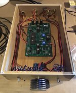
As the DIY store was absent of the “completion parts kit” I consulted NP’s list and sourced directly from Digikey. Chassis is bamboo w/plexi top, volume knob is a vintage CPU heat sink. No ringing whatsoever (have not damped the ‘tube in any way), and best of all it sounds great. Thanks to 6L6 for the well done assembly guideline.
As the DIY store was absent of the “completion parts kit” I consulted NP’s list and sourced directly from Digikey. Chassis is bamboo w/plexi top, volume knob is a vintage CPU heat sink. No ringing whatsoever (have not damped the ‘tube in any way), and best of all it sounds great. Thanks to 6L6 for the well done assembly guideline.
Attachments
Hearing this kinda troubles me -- what you're saying is that one cannot trust the voltage setting to accurately reflect the actual bias applied to the tube?
I remember reading somewhere that the voltage setting was an indirect way to set the bias because a meter would load down the primary spot. I wonder how high the impedance of the meter has to be in order to set the bias directly. Any chance of measuring the bias directly?
The impedance on the plate of the tube is quite high, just look at the 300k resistor. If you measure it with respect to ground it will load it to an inaccurate value.
If the jfet that follows it is running at Idss as intended, then it's Source will be at that same voltage.
Here's a trick: you can measure the voltage from Gate to Source with a portable DVM and add / subtract that from the Source to Ground reading and check the calibration. If the Vgs of the Jfet is 0 then it is 100% accurate.

Hi, I’m putting together a b1k from my own parts(no kit) Looking in my parts bin I have the choice between Nichicon Muse BP 10uf 50v , Silmic II 10uf 100v or 25v (made in Thailand), or some Jantzen zcaps (2x1uf, 2x2.2uf, and 2x10uf).
My question is what is the best choice between these for coupling caps?
Btw going with toshiba jfets so don’t mind going overkill with pp caps, if it actually gives any benefit 🙂
My question is what is the best choice between these for coupling caps?
Btw going with toshiba jfets so don’t mind going overkill with pp caps, if it actually gives any benefit 🙂
@ Golyd
After my B1K experience go for inputs and outputs SilmicII , in the center Muse PB pair,
then bypass with no polarised caps ~ 2uF 🙂 Sound great
After my B1K experience go for inputs and outputs SilmicII , in the center Muse PB pair,
then bypass with no polarised caps ~ 2uF 🙂 Sound great
Tanks for the advice Soundhappy! did you try different solutions before settling on this combination? Like only pp or elko? I’d much prefer single caps due to space on the pcb, but can always manage to it if it’s beneficial 🙂
Yes I have try only electrochemicals Simic II and Nichicon then only polypro ( big size )
Mixture of electrochemicals bypassed with small size ~ 2uF pp sound fantastic
Mixture of electrochemicals bypassed with small size ~ 2uF pp sound fantastic
- Home
- Amplifiers
- Pass Labs
- B1 with Korg Triode