Thimios is very kindly assembling these boards for me.
In simple terms it will be a four channel volume control with both of the volume boards controlled by the single control board. All four channels need to be controlled with the same volume levels from the controller signals.
The volume boards will be mounted at the rear of the chassis and the control board on the front panel, connected by a ribbon cable.
My assumption is that the volume boards will be stacked.
I think the easiest way to think about the stacking requirement is to assume there is no separation between the control and volume boards, so it is a simple three-layer stack. In that respect it doesn't really matter whether the control board has pins or sockets on its rear face as long as the other boards have their headers to enable them to be stacked correctly.
Thanks
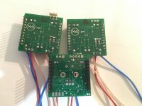
Other solution:
a cable for the rotary encoder to the front and stack all boards.
Like this 😉
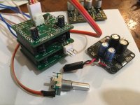
Think I'm ready for basic sound, channels have been selected, 3.3V set to internal, encoder on flying lead, 15V supply ready.
A cup of coffee and I'll slap this in my Dynalo. Fingers crossed.
Attachments
Other solution:
a cable for the rotary encoder to the front and stack all boards.
Then I would need more long cables to connect the display module.
Like this 😉
Think I'm ready for basic sound, channels have been selected, 3.3V set to internal, encoder on flying lead, 15V supply ready.
A cup of coffee and I'll slap this in my Dynalo. Fingers crossed.
You need to wire the encoder push button too.
Ok. now i see that is version 2,so i don't know if this buttun is used.
Last edited:
Thimios is very kindly assembling these boards for me.
Thanks
Ray, if you need SMD work doing mate, I'm your man in the UK 😉
You need to wire the encoder push button too.
Ok. now i see that is version 2,so i don't know if this buttun is used.
Yeah the encoder is not push button, as far as I can see the three pins are good.
I'll take another look, I have a pushy encoder spare.
I read the ver.2 manual now.
You need the encoder push button. 🙂
Thanks for spotting that Thimios, will swap with the push encoder
Ray, if you need SMD work doing mate, I'm your man in the UK 😉
Cheers, I may take up that offer sometime.
That said, I feel a bit inadequate and embarrased at shying away from smd soldering after some bad experiences in the past, mainly using a hot air station. So, yesterday I took the plunge and attempted to solder up some smd boards. The boards are switcher power boosters, designed for Nixie tubes, and use mostly larger format parts but do have an 8-legged IC and a couple of 805 sized decoupling caps - I took my time and soldered each part by hand (and used magnifier goggles). They actually look OK and both of them worked first time so maybe I should be brave in future;

12VDC in, adjustable 160-200VDC out - they're to power a DAC I/V stage based on Russian sub-miniature tubes.

Sorry for the off-topic post.
Thanks Thimios. I'm still not sure I could do something like the Muses or controller chips on Meldano's boards.
Got a problem, no sound, Can someone spot something?
L channel selected pins 1 & 2
R channel pins 2 & 3
Controller board 3.3V supply selected pins 2 & 3
I'm getting +/-15V at X1 connector pins 1 & 3 ok
Getting 3.25V from controller reg ok
All pins are soldered, tried both types of encoder.
R5 & R6 pull up resistors on controller board are omitted, J1 is open
Attachments
Please connect the status led / ir receiver and check the controller function by teaching the ir functions.
Daniel
Daniel
Remote control not required, I don't want it really.. I understood from the manual that without infrared data default values are loaded?
So this absolutely needs a remote to work? I only want basic volume control with single input.
So this absolutely needs a remote to work? I only want basic volume control with single input.
OK part ordered, please update manual or first post to recommend a remote control, which one are people using?
What LED?
What LED?