Just finished my BA2018 preamp project, and wish to thank Wayne and other contributors for a good diy project. I built it with boards from the diyaudio store (very nice) and parts from Digikey, housed in a Sescom aluminum box that had been aging for some 20 years. The finished line amp looks good and sounds great.
Had a few minor problems due to my own parts substitutions using parts on hand. Used a laydown type pot P1 that made tight fit for the standoff hardware. Used value 330 for C5 and C6 that also was tight fit.
This was my first project with SMD parts. Everything works, so I guess I did not fry the little fellows with my big fat iron. The SMD parts are too small - I am glad that SMD is probably just a fad and won't catch on.
Glenn
@Obtoiam
Thanks for the compliment. After may attempts at trying to drill holes and make cut outs by hand I gave up. I just couldn't get the results I wanted. So I drew it up using the Front Panel Design software (free) and had Gianluca and the nice people at Modushop in Italy do the rest. I am REALLY pleased with the results and have had them do a few front and rear panels for me now. It's not especially cheap, but in my mind well worth every penny.
Thanks for the compliment. After may attempts at trying to drill holes and make cut outs by hand I gave up. I just couldn't get the results I wanted. So I drew it up using the Front Panel Design software (free) and had Gianluca and the nice people at Modushop in Italy do the rest. I am REALLY pleased with the results and have had them do a few front and rear panels for me now. It's not especially cheap, but in my mind well worth every penny.
Exojam: Mr. Hui has ensured me 20k works well with SS gear upstream. I went for that, but haven’t tried it yet. I see others say the same earlier in this thread, that 20k-ish is fine, but that higher can work too. I ordered both 20 and 50, so we’ll see what works best.
Leeuwarden: can’t remember the exact voltage for a B1, but is it not around 24 volts like Dirk uses? Wayne has said (if I remember correctly) that 29v is OK too in this thread, parts are rated a lot higher than that.
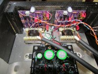
Here are some in-progress photos. Next move is to mount and solder the ground loop breaker, seen in the pics near chassis ground.
As said my latest work had been finishing the front and back panel. Also note the red and blue LED on the front. When I switch the rails off, the red light turns on for standby. When I switch them on, the red light turns off and the blue LED lights up. Pretty neat imho. Don’t quite like the look of colored LED lenses on the front, ideal would be LEDs that turn dark/colourless when off instead of native color. Looks kinda like an arcade machine, but who cares for now.
Note that the filtered AC inlet is connected straight to PSU without switch, and is fused after the transformer, with the jumper right after which I have chosen to connect a switch to mounted on the faceplate. I have an extra switch and an external fuse that I consider adding later, but for now this works quite smoothly.
Not entirely happy with the metal work, it was a mess, but think I managed to cover up most of the errors 😀
Regards,
Andy
Andy,
That is a gorgeous build you have there!
Where did you get the chassis from?
James
Just to confirm the wiring…
Hi William and all others
Sorry to bother you with this again, but...
I am finally trying to follow your footsteps and hooking up the cinemags.
Thanks for sharing all the infos...
I'm a bit stuck in trying to relate the picture of your work with the schematic...
Attached are
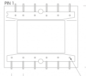
drawing of the CMOQ-4, viewed from underside
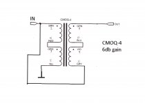
wiring diagram (which you provided)
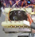
2 pics of how you did it...
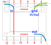
The wire-bridges on the CMOQ-4 are obvious. But I am not sure about the input/output…
- INPUT (from line-stage) is at pin 2
- OUTPUT (to output-connector) is at pin 11
- GND (both from input + output are at pin 5
Is this the way to go?
(I still don't "feel" schematics, so the gap between the looks of the real transformer and its schematic representation make me feel dizzy... took me 3 days to understand the pin-numbers run clockwise around the thing, and not in two rows left-to-right)

thank you
david
Hi William and all others
Sorry to bother you with this again, but...
I am finally trying to follow your footsteps and hooking up the cinemags.
Thanks for sharing all the infos...
I'm a bit stuck in trying to relate the picture of your work with the schematic...
Attached are
drawing of the CMOQ-4, viewed from underside
wiring diagram (which you provided)
2 pics of how you did it...
The wire-bridges on the CMOQ-4 are obvious. But I am not sure about the input/output…
- INPUT (from line-stage) is at pin 2
- OUTPUT (to output-connector) is at pin 11
- GND (both from input + output are at pin 5
Is this the way to go?
(I still don't "feel" schematics, so the gap between the looks of the real transformer and its schematic representation make me feel dizzy... took me 3 days to understand the pin-numbers run clockwise around the thing, and not in two rows left-to-right)
thank you
david
Attachments
Andy,
That is a gorgeous build you have there!
Where did you get the chassis from?
James
Hi, James! Thank you so much, really appreciated! Though I must admit I have some trouble with the right channel of the WLS after a miswiring, so must be redone.
Chassis is from Modushop, Hifi2000, they have a website and also I think it all can be ordered from the store. The chassis is Galaxy 388, with UMS bottom plate, and the knobs are also Modushop/Hifi2000 =)
Regards,
Andy
Hi David, I will try to edit the transformer drawing to hopefully make it more clear. I'm at work right now so it will be later on today. Output connector goes to pin 8. There are three jumper wires on the transformer, as seen on my picture you attached there: 3-4, 9-10, and 2-11. And yes, you are correct, all grounds go to pin 5.
@myleftear; @william2001
Any reason you guys are using the Cinemag transformers for 1:2 (6dB step up gain) when you can set various gains (by adjusting R16/R17 ratio) on the WBA2018 anyway?
https://www.diyaudio.com/forums/gro...fier-hpa-melbourne-db-buy-56.html#post5819841
Perhaps galvanic isolation or just cause you have a pair of Cinemag's you'd like to use...
Best,
Anand.
Last edited:

Where did you buy them?
CineMag CMOQ-4LPC Audio Übertrager, 49,80 €
BTW, @poseidonsvoice , I chose to go that route because this linestage is just right for driving an amp with gain (ACA et al) but comes to its limits when plugged into my bigboy f4… so I’m on a switchable ouput-thing, like, output 0dB/+6dB (no idea if those numbers are correct, but you get the idea)
Building a switched resistor-array woulb be possible to I guess, but inserting a switch and stuff into the midst of such a circuit, I didn‘t dare.
Last edited:
How much swing do you achieve with your solution? What’s your rail voltage?
Learning, so I ask. Plus I might do an F4. We shall see.
Learning, so I ask. Plus I might do an F4. We shall see.
It should give +6dB (as by William, I‘m not yet there... and couldn‘t tell you a number...)
In its default configuration, the wls nicely drives f4, but it‘s cranked up pretty high at around 3-5 o’clock, then it’s enjoyably loud but not more. (Kef 101/2, 86dB...)
In its default configuration, the wls nicely drives f4, but it‘s cranked up pretty high at around 3-5 o’clock, then it’s enjoyably loud but not more. (Kef 101/2, 86dB...)
repeater as that one, connected as autoformer , can give you gain of either 2V/V or 4V/V
that being 6db or 12db
Rout going up 4x or 16x
that being 6db or 12db
Rout going up 4x or 16x
- Home
- Amplifiers
- Pass Labs
- Wayne's BA 2018 linestage