Last edited:
Not sure that's @rock12's issue... not saying it isn't either, I'm no expert—but I haven't tied the tranny shield directly to the same contact point as IEC ground in any of 8 builds (mono blocks, not including preamps) preferring to keep it as short as possible, I always ground it right next to the donut....zero PSU dramas to date, baring LED flipping. I DO see a couple of indications of maybe suspect soldering welds. Would like to see the bottom of the board...Why everything is "fine" with phone vs other sources...beyond my current knowledge.
Rock12-
Where is the CL60 on the PSU board connected... the photo only shows the chassis connection.
Post a photo of the connection side of the PSU please.
Put the purple transformer lead to the screw that is chassis ground and forget about it, that is probably not the issue.
Where is the CL60 on the PSU board connected... the photo only shows the chassis connection.
Post a photo of the connection side of the PSU please.
Put the purple transformer lead to the screw that is chassis ground and forget about it, that is probably not the issue.
The cl60 is only there as an inrush limiter. I will move the purple wire over. The purple wire was connected on to ground on that far side and when I checked I noticed it was solder was disconnected. The side with smoked resistors is on the opposite side of the amp overheat. If you look closely on the left side of pic near center of the amp you con see the black streak where the trace raised up
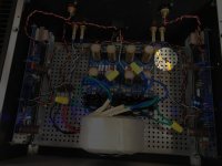
Here’s pic
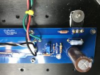
On a separate note, your power supply capacitors look rather small. What are their ratings? (Eg capacitance, rated voltage)
Probably they are fancy Nichicon Gold stuff, but you might consider more capacitance to reduce power supply ripple.
Jusr my 2cents
Had some time to check voltages my transformer puts out 19.5 volts AC both sides but on the output I have 50V and 25V. 25V is design so I will pull board. What do you think failed. The smoked resistors are on the 25V side
My detail. Voltages left to right. V- 0 volts, ground 25 volts, ground 25volts,V+ 50 volts yet the amp works. How strange. Think I will use a bridge
Disconnect everything from your Euroblocks on your PSU. Remove the connections to the amp boards and your ground lift or anything else. Just have the safety earth to chassis, toroid and PSU wired.
Measure again.
To ensure clarity measure here at the output near the Euroblocks.
V+ (Red Probe) to GND (Black Probe)
V- (Red Probe) to GND (Black Probe)
Measure again.
To ensure clarity measure here at the output near the Euroblocks.
V+ (Red Probe) to GND (Black Probe)
V- (Red Probe) to GND (Black Probe)
As IAIMH says, place the black probe on PSU ground, move only the red probe.
PLEASE post a photo of the output side of your PSU.
PLEASE post a photo of the output side of your PSU.
With the power supply unhooked on the desk when I check continuity between the 4 outputs at one check the are all connected and moments later I have no continuity
Rock12
We are trying to help get your amp working properly...
Please post a photo of the output side of your PSU. You’ve got something incorrectly attached, but we need to see the connections to determine exactly the issue.
We are trying to help get your amp working properly...
Please post a photo of the output side of your PSU. You’ve got something incorrectly attached, but we need to see the connections to determine exactly the issue.


I'm about to start building this for an Aleph J, but would of course like to have something that will work with other amps. So a few questions.
1. Is it worth going with 50V caps to future-proof it?
2. The BOM talks about 'optimal values' for the input snubber resistors and capacitors. I've looked through some of the pages here, but there are a lot of them! Are their values that are known to work well in this application?
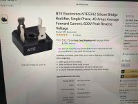
3. Is there any reason not to use monolithic bridges?
1. Is it worth going with 50V caps to future-proof it?
2. The BOM talks about 'optimal values' for the input snubber resistors and capacitors. I've looked through some of the pages here, but there are a lot of them! Are their values that are known to work well in this application?
3. Is there any reason not to use monolithic bridges?
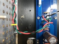
That was connected to st_v- lug in the right hand corner. Hmmm I think that should have been board ground where the two sides come together
I'm about to start building this for an Aleph J, but would of course like to have something that will work with other amps. So a few questions.
2. The BOM talks about 'optimal values' for the input snubber resistors and capacitors. I've looked through some of the pages here, but there are a lot of them! Are their values that are known to work well in this application?
I'm only qualified, just barely 🙂, to weigh in on number 2.
Simple, no-math transformer snubber using Quasimodo test-jig
and there's a thread of "results only":
Quasimodo results (ONLY)
- Home
- Amplifiers
- Power Supplies
- diyAudio Power Supply Circuit Board v3 illustrated build guide