1. Is it worth going with 50V caps to future-proof it?
3. Is there any reason not to use monolithic bridges?
The caps live longer when they aren‘t driven to their limits. (And there‘s something about less ripple if I recollect it correctly)
The bridges are said to be equivalent in quality. But obviously much smaller, and no soldering around. (I chose not to use them because they are so much easier...)
I think that should have been board ground where the two sides come together
Yes
That was connected to st_v- lug in the right hand corner. Hmmm I think that should have been board ground where the two sides come together
Bear with me, I've been following along at home and I'm trying to understand how this power supply *ever* worked with the chassis attached to V-.
Is it because there was no connection between PSU ground and the chassis and even with V- connected to earth, that doesn't complete a (short) circuit?
How did connecting a device cause the short to manifest? Did it somehow create a connection between PSU ground and the chassis? Or did it complete a circuit through the "ground" connection of the wall wiring?
Perhaps since it was connected to a phone there was no earth, and once it got hooked to another device connected to mains and grounded, the problem showed up?
Yes .
Once it was attached to another device the hot chassis found earth through the RCA connection, to the other device, to ground.
That the path was through the resistance of the CL60 in the wrong spot was what kept it from being on a hair trigger and just got the PSU resistors toasty.
Once it was attached to another device the hot chassis found earth through the RCA connection, to the other device, to ground.
That the path was through the resistance of the CL60 in the wrong spot was what kept it from being on a hair trigger and just got the PSU resistors toasty.
Does anyone have Mouser part numbers for TO-220 insulators and the accompanying insulator washers?
Hi all, this is a super newbie question. My electronics is so rusty now but I hope someone can help me out here. The recommended transformer call for 18vac out but how can it achieve 24vdc with all the voltage drop across the diode and resistors? I mean how does it go up from 18 to 24? ��
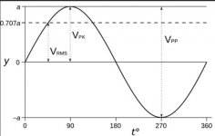
18 vac is an rms value. The peak value of 18v rms is 18 multiplied by root 2 which is 25.4 volts. Or as shown here you can divide the rms value by 0.707. Either method gives the same result.
That peak voltage is the voltage a diode rectifier and capacitor will charge up to (less volt drop losses across the diode/s).
Your meter would show 18 vac and a scope would show 50.8 volts from top to bottom, in other words the peak to peak value.
That peak voltage is the voltage a diode rectifier and capacitor will charge up to (less volt drop losses across the diode/s).
Your meter would show 18 vac and a scope would show 50.8 volts from top to bottom, in other words the peak to peak value.
Attachments
Separate chassis power supply question
I am finalizing the design of a power supply in a separate chassis for my Aleph J build. I will use this supply for other DIY Pass amps in the future, and have a few questions with regard to the use of an umbilical, and the addition of a final capacitor bank in the amp.
My supply uses an Antek 500VA torroid and 8X 33000 uF capacitors for a total of 264000 uF or 132000 uF per rail. This is a lot, but my intention is to add an additional torroid into the power supply chassis for a dual mono supply and then split the available capacitance so that each supply will have 132000 uF. For know I can divide these capacitors up so that I can put one or two per channel into the amp chassis instead of in the power supply chassis. The universal power supply filter is a CRC filter, but I coulld make it a CRCRC filter instead with the final RC in the amp chassis.
My questions are...
1. Is putting the final RC in the amp chassis a good idea?
2. How much capacitance of what I have available should be in the final C?
2a. Is there a minimum amount of capacitance required in each stage?
3. Is the resistance of the umbilical wire between the amp and power supply chassis sufficient, or should I add resistance? I have a bunch of .1 Ohm 20 Watt resistors on hand that I can also put in parallel if required.
4. I also have a selection of film caps that could be used in parallel with an electrolytic for the final RC stage in the amp chassis. What should this final stage look like with respect to the values of the primary electrolytic and the film caps in parallel?
Last edited:
The answer to (1) and (3) both depend in part on how long your umbilical is.
The first C needs to have a high enough ripple spec to take what's coming out of the bridge rectifier. This will effectively set its minimum capacitance. The other stages don't have a minimum.
If you're going to use parallel film caps I personally think they belong on the amp boards next to the consumers, not in the PSU. The parallel caps need to have capacitances far enough apart not to introduce parasitic oscillations.
*If* you do small electrolytics+film caps on the amp boards *and* have a short umbilical I think I'd be inclined to put the CRC in the PSU chassis and consider the umbilical your second R before the final C on the amp boards.
If not, I'd be inclined to put the CR in the PSU chassis and the second C in the amp chassis.
The answer to (1) and (3) both depend in part on how long your umbilical is.
The first C needs to have a high enough ripple spec to take what's coming out of the bridge rectifier. This will effectively set its minimum capacitance. The other stages don't have a minimum.
If you're going to use parallel film caps I personally think they belong on the amp boards next to the consumers, not in the PSU. The parallel caps need to have capacitances far enough apart not to introduce parasitic oscillations.
*If* you do small electrolytics+film caps on the amp boards *and* have a short umbilical I think I'd be inclined to put the CRC in the PSU chassis and consider the umbilical your second R before the final C on the amp boards.
If not, I'd be inclined to put the CR in the PSU chassis and the second C in the amp chassis.
JeffYoung: The umbilical will be 5-6 feet long. I have a large selection of stranded silver plated copper wire in Teflon on hand, from 10 gauge.to smaller.
The capacitors I have are 33000 uF. With respect to there being no minimum capacitance for later stages, when I tried a 100 uF cap as the final C value in PSUDII, the voltage graph looked very ragged. In the amp, I can put one of the 33000 uF caps and some film capacitors in parallel, but I only have film cap values up to 100 uF. I’ve seen photos in the past of DIY Pass amps with metal can film caps in the amp chassis, but I don’t know if they were in parallel with electrolytics.
While there's no minimum, the R values need to be adjusted to the C values. A final C of only 100uF would need a very very small R to go with it.
Personally in your situation I'd just put one 33,000uF in the amp chassis and call it a day. But paralleling a 100uF film with it would be fine too. (Or putting parallel 220uF electro + 1uF films on the amp boards.)
Personally in your situation I'd just put one 33,000uF in the amp chassis and call it a day. But paralleling a 100uF film with it would be fine too. (Or putting parallel 220uF electro + 1uF films on the amp boards.)
- Home
- Amplifiers
- Power Supplies
- diyAudio Power Supply Circuit Board v3 illustrated build guide