Thanks ZM. I got your simulation working. I have no idea which LU1014 spice model is most believable.
well, like in a Joke about Philosopher, Math guy and Engineer , with gorgeous girl in a middle of big room ( getting to her, in each step advancing exactly half distance) ............ sims got me close enough, then who cares about sims

I have about 7000 of them. If someone wants to organize a group buy let me know.Any reliable source of real LU?
Also we are considering a diy f3 kit for the store. Maybe ludef kit as well?

 Greetings
I am interested in performing matching/sorting. If there was a production procedure for matching devices for the F3, I would be willing to do it. Maybe the DIY Audio Store offers matched pairs/quads?
Nelson Pass nails it just a second time.
If something like a new amp in the store would happen, ooowh!
For everything (here in this community, the store, passdiy etcetc) manymanythanks, anyway !
If something like a new amp in the store would happen, ooowh!
For everything (here in this community, the store, passdiy etcetc) manymanythanks, anyway !
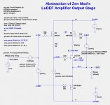
Here is have an abstracted version of ZM's LuDEF to allow both simple experiments and to more easily understand the essential parts of the circuit. Attached are 2 files: the LTSpice asc file, and the Cordell Models, needed for the IRFP9240. Place these files in the same directory as the files ZM provided in post #178.
Attachments
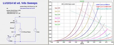
Here is another simulation file for plotting the triode curves for the cascoded LU1014.
The triode curves in plot on the right was generated by this simulation, but the load lines were manually added to the plot. The load lines were generated from the LuDEF simulation asc file.
The triode curves in plot on the right was generated by this simulation, but the load lines were manually added to the plot. The load lines were generated from the LuDEF simulation asc file.
Attachments

until they go wild, Umbrell-ed 
ZM expecting arrival of Babelfish M25 R.2/SET pcbs
so, dual pcb, again
first one already known but improved Berserker
second one , SIT amp without SIT, for us mere Mortals
again - All The Glory........ or Major Flop/public disgrace

ZM expecting arrival of Babelfish M25 R.2/SET pcbs
so, dual pcb, again
first one already known but improved Berserker
second one , SIT amp without SIT, for us mere Mortals
again - All The Glory........ or Major Flop/public disgrace
Here is have an abstracted version of ZM's LuDEF to allow both simple experiments and to more easily understand the essential parts of the circuit. Attached are 2 files: the LTSpice asc file, and the Cordell Models, needed for the IRFP9240. Place these files in the same directory as the files ZM provided in post #178.
R8 varying - if one prefer total symmetry of positive and negative gate voltages
RM2S?
investigating modulated Uds for LU?

I have about 7000 of them. If someone wants to organize a group buy let me know.
Also we are considering a diy f3 kit for the store. Maybe ludef kit as well?
Happy to help out and organize a group buy. I can help Woofertester with it or organize it solo on the group buy page. Just let me know what I can do to help.
Happy to help out and organize a group buy. I can help Woofertester with it or organize it solo on the group buy page. Just let me know what I can do to help.
I will be happy to only do matching and curve tracing for those that wish to have that performed. That will involve some shipping of parts around which is trivial as these parts are small. I have 150 pcs and they take up very little space.
I will be happy to only do matching and curve tracing for those that wish to have that performed. That will involve some shipping of parts around which is trivial as these parts are small. I have 150 pcs and they take up very little space.
I would also be happy to let woofertester do the matching, and help with mailing to individuals.
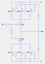
Oops. I just noticed that the PFETs in post #195 are upside-down (stupid default part orientation in LTSpice). Here is the corrected image.
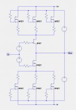
More explanation about that topology. It allows for the driver FETs J1 and P1 to have low Vds values, but high idle currents, while the remaining NFETs and PFETs have high Vds and a fraction of the idle current. This allows for a high power amplifier to be driven by just the two undegenerated FETs J1 and P1.
I suspect this has been tried before, maybe in a commercial product. Anyone know?
Attachments
- Home
- Amplifiers
- Pass Labs
- LuDEF