worth looking in Papapatents, as first place
benefits you're expecting?
One could build a 100W/ch, 200W/ch, or more amplifier without the degeneration using the single-cascode multiple-FET topology of post #200. Not that I need such a monster, just a theoretical exercise. I have no idea how far the LU1014D could be pushed. Perhaps to 3A idle current, which would be enough for 100W.
not that I would trust in those tiny pins, for anything substantial dynamically
100W means 80Vpp envelope, which means peak current in range of 5A with benign 8R load
call me a Chicken, but without at least 2 pcs of LU in parallel, I wouldn't even try 100W amp, more for more
of course , one can make non-degenerated Stasis OS, using tiny buggers as drivers/fillers
100W means 80Vpp envelope, which means peak current in range of 5A with benign 8R load
call me a Chicken, but without at least 2 pcs of LU in parallel, I wouldn't even try 100W amp, more for more
of course , one can make non-degenerated Stasis OS, using tiny buggers as drivers/fillers
ZM: How can you parallel the "tiny buggers" without degeneration? Wouldn't there be "current-hogging" issues? The all of the Stasis schematics I have seem show degenerated BJTs in the output stage.
Running that much current through these things will require better heatsinking. They are tiny - much smaller than TO220. JPS64 and I are thinking of making an aluminum core PCB adapter that will allow these LU1014’s to be mounted and resemble a TO-247 package. It will provide a heat spreader to broaden the area for thermal flux to pass to the heatsink.
5A x 20v drop is 100w dissipation. I wouldn’t want to put more than 20w each on these so we are talking 5 LU1014’s in parallel for a 100w amp.
5A x 20v drop is 100w dissipation. I wouldn’t want to put more than 20w each on these so we are talking 5 LU1014’s in parallel for a 100w amp.
@lhquam
well, that's exactly the trick ..... I mean - no trick but catch
of course, I didn't finished the sentence - really don't know how to parallel them without Rsource and is it even possible, even with all precautions in matching ...... thing which needs to be tried in real life
when I mentioned Stasis,this came to mind - adequately biased NP pair (of JFet + Mosfet) but also just one pair of big mosfet outputs, which is possible if we use big Pucks
at least logical for me - when going Square Law route, paralleling is either tricky or impossible, so using single pairs is pretty much sole viable solution
in this moment I see it as working, dunno later
frankly , not soaked enough with coffee today......
Attachments

Running that much current through these things will require better heatsinking. They are tiny - much smaller than TO220. JPS64 and I are thinking of making an aluminum core PCB adapter that will allow these LU1014’s to be mounted and resemble a TO-247 package. It will provide a heat spreader to broaden the area for thermal flux to pass to the heatsink.
5A x 20v drop is 100w dissipation. I wouldn’t want to put more than 20w each on these so we are talking 5 LU1014’s in parallel for a 100w amp.
I'm not so scared of heat, as I'm scared of current through tiny bugger
for all sane currents, heatsinking is adequate and all you can do with any other arrangement is just going to ease mounting
not that that goal isn't worth pursuing
I just found this article about the current limits of MOSFET bond wires:
http://www.aosmd.com/res/application_notes/mosfets/Continuous_drain.pdf
Based on the LU1014D datasheet, the circular cross section of the leads appear to be about 0.4 mm^2 which corresponds to about AWG 21 wires.
http://www.aosmd.com/res/application_notes/mosfets/Continuous_drain.pdf
Based on the LU1014D datasheet, the circular cross section of the leads appear to be about 0.4 mm^2 which corresponds to about AWG 21 wires.
Last edited:
Magura had his LU soldered to copper sheet, then using massive Carbon heat spreaders, in his circular shaped beasties
Thanks for that. I sort of recall now. The copper blocks look nice. Doesn’t solve the problem with tiny leads. Hopefully the adapter/helper PCB will give substantial spots for leads to be soldered to.
Thinking about current hogging and bond wires, couldn't a parallel/tripled/etc F3 be done with separate output caps for each F3 clone, and tying them together after the caps?
I'm definitely interested in a group buy for the F3, by the way 🙂 Our F3 clone is wonderful, but I've been playing with low resistance drivers lately
(On a similar note, maybe a F8 turbo could be done the same way)
I'm definitely interested in a group buy for the F3, by the way 🙂 Our F3 clone is wonderful, but I've been playing with low resistance drivers lately
(On a similar note, maybe a F8 turbo could be done the same way)
Last edited:
well, make your mind - either low/semi power A class amp, finely tuned as Minarelli 50cc ...... or big honking/low rails/high current amp
hard to have everything ....... big pucks are not liking low voltages, IRFP sorta same , LU right there, but wimpy wires .......
of course, if you introduce output xformer, The World is your Oyster
it seems changing back to sane impedance drivers is simplest

hard to have everything ....... big pucks are not liking low voltages, IRFP sorta same , LU right there, but wimpy wires .......
of course, if you introduce output xformer, The World is your Oyster
it seems changing back to sane impedance drivers is simplest
Point well taken, I'm making a 4 channel speaker with the 6-24, so LuDEF for the woofers will have the clean power anyway.
...But if I could parallel the HF amps to play with loadlines or use them on the woofers..... (49% justification, 51% Greedy Boy 🙂
Edit:
I use some toroidal autoformer on the output to play around as well, but we have some ESLs that benefit from the current for HF capacitance. But those ESL's are justifying a HV Vfet amp plan already.
Last edited:
don't let me, or anyone else, to spoil your fun
🙂
progress is made tnx to dreams of impossible, not playing safe, as we Geezers do
🙂
progress is made tnx to dreams of impossible, not playing safe, as we Geezers do
Oh not at all! My fulfillment wouldn't have been anything like this if not for you and Papa's and everyone's community here. And the plumbing schematics in the F5 article
I just found this article about the current limits of MOSFET bond wires:
http://www.aosmd.com/res/application_notes/mosfets/Continuous_drain.pdf
Based on the LU1014D datasheet, the circular cross section of the leads appear to be about 0.4 mm^2 which corresponds to about AWG 21 wires.
American Wire Gauge Chart and AWG Electrical Current Load Limits table with ampacities, wire sizes, skin depth frequencies and wire breaking strength says 21 AWG should be able to handle 9 Amps; another chart I got elsewhere says about 7.25 Amps.
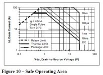
You have to adjust Vds against Ids to be at or near the sweet spot, and at those
currents you might find yourself at higher dissipation than you allowed for.
currents you might find yourself at higher dissipation than you allowed for.
- Home
- Amplifiers
- Pass Labs
- LuDEF