in most cases thinking what Pa was thinking is ............. nogood
with me, it ends either in headimplode, or in overthinking
in any case, whenever he gets insight of that, I know he had some sweet laugh that day
btw, same sim as you did up, with IXYS pucks (;;; IXFN140N30PQ and IXTN40P50PQ SPICE models from Lynn Quam) - THD at 200W is slightly lower and still dominant 2nd
rails 65V, Iq 3A4 ........ but it can go down to 3A1 without KlunK!ing
Real Men territory
Last edited:
Xrk971:
You ask some good questions:
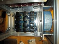
Could you show more views of your packaging? I am always interested in packaging techniques, particularly ones that facilitate prototyping.
- I suspect there might be FETs capable of 150W+ idle power dissipation, but extraordinary measues are required to carry the heat away from single devices. BTW: what IXYS FETs did you use?
- By paralleling 4X TO-247 FETs I limit the idle power dissipation to under 45W each and spread the heat across a "more normal" heatsink.
- You are correct to be concerned about all of the current through the tiny leads of the LU1014D.
- It should be deal with 6.6W-10W idle power dissipation of the LU1014D.
- Nelson used goop to anodized aluminum for the F3.
- F3 cloners soldered them to copper spreaders.
- Another option is goop to a copper spreader atteched to the heatsink with good and insulator.
If by packaging you mean how to mount an IXYS TO-264 to a Dell CPU cooler, more is shown here.
Clamp bar, flying leads, ceramic insulator, and goop. Photo shows second TO-3P BJT used with only 15W dissipation (part of cap Mx). So total dissipation was 165W. Noctua fan was on not lowest speed but one tick above. Still very quiet.
Get the Dell coolers with a big fat copper surface.
The IXYS was IXTK90P20P P-channel. This was for a slightly different config than basic Mofo.
Last edited:
Do those pucks operate within the SOA? Sounds like CPU cooler time for the pucks.
200W voltage envelope, still less than 10A which I believe is magic number
good thing that Physics ...... current peak is when voltage across device is on minimum , and the other way
XRK, by packaging, I think Lynn is referring to the slick modular frame system that you are using.

.....Catch is** - now I'm in the loop of working on finishing ( damn, yes, all tried and confirmed in prototypes and all having finished pcb files) some 15 different amplifiers, more or less different and more or less similar, but in most cases being worthy of realization
** so Mighty ZM being confused,to live in outer world and work on logistics for kits, or to proceed with further amps
Please be assured that your efforts are appreciated.
...although I can't understand how you could possibly be confused by 15 simultaneous amp projects.
XRK, by packaging, I think Lynn is referring to the slick modular frame system that you are using.
MakerBeam rocks!
https://www.amazon.com/dp/B06XJ2CMWM/ref=cm_sw_r_cp_api_glt_fabc_2Q0BJCD2SKH5A53NK7TD
Building this amp with laterals (162 1058) could allow to skip the whole bias circuit? Using simple resistor or diode bias network. Or the LU tempco would still make the bias to drift a lot with temperature?
The lower transconductance could affect more or less the sound...
The lower transconductance could affect more or less the sound...
if you think about just laterals in OS ( without LU) then yes - possible ( and certainly already done), but that is whole another amp
if you think on laterals instead of verticals, in same schematic, there is no any benefit of that ........ and you'll still need proper voltage shifter in front of LU, thus proper biasing circuit
name of the game with Square Law arrangement is to get as much of Berserking you can, while laterals are wimpy Berserkers
Last edited:

Bosch aluminum profiles also are superb for larger builds. They can be water cooled even as a heatsink.
Bosch-Rexroth in|MOTION4
Bosch-Rexroth in|MOTION4
What is the gate to source voltage of the LU when the Amp is biased correctly?
I know it depends on each LU but as an average is it - 1v? Or so?
I know it depends on each LU but as an average is it - 1v? Or so?
using the LU "triode cell" it could be possible to build a MoFo like follower loaded with a choke on the source.
If the DCR of the choke is 0.5R and the bias is 2A the voltage at the source of LU is 1V relative to ground.
Referencing the gate of the LU with a 100K resistor to GND it should be biased correctly.
Then no need of a coupling cap at the input
Of course you need a cap to couple the speaker at the output
Could-it work and sound nice?
- Home
- Amplifiers
- Pass Labs
- LuDEF