FlaCharlie: unfortunately the hum does have harmonics that are of higher frequency. I should have mentioned this prior, as it is relevant. It’s not just a low frequency hum as I’ve heard before from other amps.
p.s. Try to separate hum source, disconnect 100nF capacitor leg from EL84 grid. If hum remains, the first stage OK.
I will do as you suggest this evening and report back.
High frequency hum harmonics (sounding like drill motor interference),
are often the result of DC power supplies that use a capacitor input filter.
The transient currents are large, and can cause ground loops.
Both B+ and DC Filament rectifier/capacitor input can cause this problem.
Do not connect the first filter cap directly to the "star", or "central" ground point.
connect the first filter cap to the second filter cap, and then from the second filter cap to the star or central ground point.
The first cap has the largest transient current, and must be connected in a very small length local loop (secondary, rectifier, first cap).
The transient current of capacitor input filters, can also cause the magnetic spray from the power transformer to have these high frequency harmonics.
A steel chassis will conduct the magnetic spray to an air-gapped single ended output transformer.
Last edited:
Pls also show us schema for filament supply. There is room to improve your PS.
Regards
minhaj: the filament supply is built according to the recommended schematic that is in the guide for Coleman filament regulators. Coleman’s actual raw supply PCB is much more compact, neater and has none of the wiring runs that mine has. This could be contributing to the problem. My supply is the same circuit though.
High frequency hum harmonics (sounding like drill motor interference),
are often the result of DC power supplies that use a capacitor input filter.
The transient currents are large, and can cause ground loops.
Both B+ and DC Filament rectifier/capacitor input can cause this problem.
Do not connect the first filter cap directly to the "star", or "central" ground point.
connect the first filter cap to the second filter cap, and then from the second filter cap to the star or central ground point.
The first cap has the largest transient current, and must be connected in a very small length local loop (secondary, rectifier, first cap).
The transient current of capacitor input filters, can also cause the magnetic spray from the power transformer to have these high frequency harmonics.
A steel chassis will conduct the magnetic spray to an air-gapped single ended output transformer.
I rebuilt the power supply and am rewiring the grounding based on your and euro21’s suggestions.
p.s. Try to separate hum source, disconnect 100nF capacitor leg from EL84 grid. If hum remains, the first stage OK.
euro21: I lifted the leg of the 100nF capacitor and that completely gets rid of the hum with silence at the speakers. I have attached a photo of the bottom as it is now with the grounds changed. I really don’t think this has anything to do with the grounding of the HV power supply and the circuit. None of the changes to the grounding have had any effect on the hum level.
Attachments

On the advice of jhstewart9 via PM, I bypassed the cathode resistors of the 30 tubes with capacitors and it eliminated the hum. I’m not sure yet what impact it will have sonically, but the hum is definitely gone. What does this mean exactly? What was the problem that was solved by bypassing the cathode resistors? Can this problem be dealt with in another manner?
It seems to me that the secondary winding that ran your Coleman Regulators were injecting noise into the 30 filament ("cathode").
Bypassing the filament/"cathode' self bias resistor shunted that noise from the secondary winding to ground.
The problem was not the Coleman Regulator.
The problem was what was coming from the floating secondary that powered the Coleman Regulator.
If you want to eliminate the bypass capacitor, you will need to find a transformer that does not inject noise to the floating Coleman Regulator/filament circuit.
Now you should enjoy listening.
Just my opinion.
Last edited:
I looked more closely the pics, especially the tube's filament parts.
I don't understand one more thing: is EL84 tubes heating not part of HV transformer?
If I look it correctly, the twisted red/yellow filament wires (bottom view: on the left side from the back to left EL84 socket, than to the right EL84 socket) come from R.C filament transformer?
Is this grounded (with two few hundred Ohms from each socket pin), or lifted to about 1/4 B+?
p.s. That's the other comment, that R.C filament transformer mains wiring near to the secondary wirings.
It seems to me that the secondary winding that ran your Coleman Regulators were injecting noise into the 30 filament ("cathode").
Bypassing the filament/"cathode' self bias resistor shunted that noise from the secondary winding to ground.
The problem was not the Coleman Regulator.
The problem was what was coming from the floating secondary that powered the Coleman Regulator.
If you want to eliminate the bypass capacitor, you will need to find a transformer that does not inject noise to the floating Coleman Regulator/filament circuit.
Now you should enjoy listening.
Just my opinion.
6A3sUMMER: I am enjoying it. It sounds very good.
Rod Coleman said that he thought the transformer that I used for the raw DC supply for the filament should be good. It’s a Hammond 229B16. He said “...it's designed for low external flux, and the split-bobbin design means low coupling of common-mode noise from the primary.” I have 3 more of the same model. The one that I used in the build was second hand and used. It looks a bit rough so maybe it isn’t good functionally? It does put out the right voltages from both secondaries. I can try a new one to see what happens. Any other transformer that I could use would also likely be an open frame Hammond with a split-bobbin.
Would snubbing the secondaries or the rectifier diodes help?
Last edited:
I looked more closely the pics, especially the tube's filament parts.
I don't understand one more thing: is EL84 tubes heating not part of HV transformer?
If I look it correctly, the twisted red/yellow filament wires (bottom view: on the left side from the back to left EL84 socket, than to the right EL84 socket) come from R.C filament transformer?
Is this grounded (with two few hundred Ohms from each socket pin), or lifted to about 1/4 B+?
p.s. That's the other comment, that R.C filament transformer mains wiring near to the secondary wirings.
euro21: The main transformer has a 6.3 volt winding that I am using for the EL84/6V6 tubes. I tucked the twisted red/yellow pair under the wooden plate that has the raw DC supply for the filaments on it, in the bottom right corner. Next to the power transformer there is a block made up of dropping resistors for the 6.3 volt winding, and I now added back the artificial centre tap resistors to ground. There was no change in the buzzy hum by adding the artificial centre tap or by lifting the 6.3 volt winding with 35 volts of DC.
I investigated the transformer for the filament supply, and it may have had one of the two primary windings terminal connectors broken off. When I was desoldering the transformer to remove it, the terminal came off along with the wire from the inlet. It may have happened just then while I was desoldering. Would having one of the two windings disconnected cause the problems I have been having with buzzy hum?
I have repaired the transformer by reattaching the disconnected terminal. Of will be ready to put back in tomorrow.
I have repaired the transformer by reattaching the disconnected terminal. Of will be ready to put back in tomorrow.
The filament is 2v and only .06a. A single AA battery will give you 1.5v and starving the filaments tends to help too.
FlaCharlie: Since I had the filament transformer disconnected, I hooked up a AA battery to each 30 filament. I also removed the capacitor on the 30’s cathode resistor to see what would happen with respect to the hum. I used a couple of brand new alkaline batteries that I had handy.
There is no hum at the speaker with the battery powered 30 filament and the cathode resistor bypass capacitor removed. There is hiss though. It’s audible at the listening position. There is also much less gain, and the sound is softer and more dull. This may be due to running at 1.5 volts. Ideally a 2 volt battery would be used for comparison. Is there a battery type that won’t generate hiss, or generate less hiss?
Battery powered filaments would greatly decrease the complexity of the amp, but as tested, they don’t hold a candle to the DC filaments with respect to sound quality.
If you -temporary- move R.C. regulator boards closer to the amp centre (there is quite a lot of space here), is the hum changing?
The 6.3V AC filament wires passes through under the regulator boards.
The 6.3V AC filament wires passes through under the regulator boards.
''Battery powered filaments would greatly decrease the complexity of the amp, but as tested, they don’t hold a candle to the DC filaments with respect to sound quality.''
Please don't conclude so early. Voltage should be spot on at first. You can use 2x1.5volt batteries in series and series resistor. You can use 1.2x2 rechargeable batteries also with a small resistor in series.
Regards
Please don't conclude so early. Voltage should be spot on at first. You can use 2x1.5volt batteries in series and series resistor. You can use 1.2x2 rechargeable batteries also with a small resistor in series.
Regards
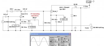
Uncommon Problems
I first noticed something odd in my amps many years ago that defied an ordinary explanation. I found there to be enough capacitance between the OPT windings & the core & between each other to make a difference in the end result. So much so that it was causing problems for my calculations of FB components to get stability.
On checking a common Hammond OPT I found the capacity from the primary to the core was ~20 pF at one end & ~200 pF from the other. So real inbalance for a PP circuit. I measured several others, they all had this sort of problem. The cause is that in common OPTs the primary winding begins at the core, there's a difference in capacitive coupling to the core from the ends of the winding. You will see the ends of the windings color coded so that the end of the wdg nearest the core is attached to B+. If it was the other way round the plate of the OP tube would have to drive a much larger capacity.
The interwinding capacities in PTs are sufficient that a small current can be coupled into a circuit, something that does not appear on the schematic.
In these simulations the conditions on the 30 filament are setup so that they look like they are driven by the external Coleman cct. The 33R resistor represents the 30 filament, 2V & 60 mA. The external filament PS is represented by the 120V 60 Hz supply at the lower RHS. A capacitive leakage current occurs thru the 200 pF interwinding coupling. The 60 Hz interference is 5 divisions on the scope about a mV p-p.
One of the example ccts on DIY was with the 26. Altho the gain thru that cct is about the same with the 30, the cathode cct is at a much lower impedance. So very little interference voltage can occur across the cathode resistor. A lot less gets to the speaker.
The 2nd sim has an insulation leakage component included. The interference signal increases to 2.5 mV p-p.
A large value cap shorts the interfering signal to common.
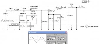
Attachments
The lower gain is due to the lower filament voltage. I only suggested using an AA because it's probably something everyone has on hand. As someone mentioned earlier, there are rechargeable 2v batteries available and that would be the way to go if you decide to use batteries. I'm not sure about the hiss.FlaCharlie: Since I had the filament transformer disconnected, I hooked up a AA battery to each 30 filament. I also removed the capacitor on the 30’s cathode resistor to see what would happen with respect to the hum. I used a couple of brand new alkaline batteries that I had handy.
There is no hum at the speaker with the battery powered 30 filament and the cathode resistor bypass capacitor removed. There is hiss though. It’s audible at the listening position. There is also much less gain, and the sound is softer and more dull. This may be due to running at 1.5 volts. Ideally a 2 volt battery would be used for comparison. Is there a battery type that won’t generate hiss, or generate less hiss?
Battery powered filaments would greatly decrease the complexity of the amp, but as tested, they don’t hold a candle to the DC filaments with respect to sound quality.
I'm using batteries on the grid to provide bias voltage, not to heat the tubes. I suggested battery heating simply as a way to determine if the hum was related to the filament supply which, apparently, it was.
To heat the various DHT inputs tubes I've been trying I use a single Meanwell 3.3v 10A SMPS, which is cheap ($10) and self-contained. AC in, regulated DC out. The Meanwell is followed by a Triad C-56U choke and a 22,000 uf 25v cap. When I had the 30 installed, I added a 5 ohm 5w wirewound to drop the voltage a bit.
The Meanwell has some adjustment range. With the above setup and the adjustment at the minimum, I was getting ~1.91v DC on the filaments so a minor adjustment gave me the nominal 2v.
Last edited:
Are you have any ruggedized EL84?Here it is corrected.
The limiting value of Va is 300V.
If you -temporary- move R.C. regulator boards closer to the amp centre (there is quite a lot of space here), is the hum changing?
The 6.3V AC filament wires passes through under the regulator boards.
I can try that again but, in past iterations, the regulators were more in the middle and still made the same buzzy humming.
''Battery powered filaments would greatly decrease the complexity of the amp, but as tested, they don’t hold a candle to the DC filaments with respect to sound quality.''
Please don't conclude so early. Voltage should be spot on at first. You can use 2x1.5volt batteries in series and series resistor. You can use 1.2x2 rechargeable batteries also with a small resistor in series.
Regards
minhaj: I will try battery filaments done properly as well. I realize that the AA batteries were not a fair test. They did eliminate the buzz though, which was the the primary reason for the test. The hiss form the batteries at the speaker was obvious. Is this a result of using the wrong battery type, or just not enough voltage?
- Home
- Amplifiers
- Tubes / Valves
- DHT driver for triode wired SE EL84, 6V6 or EL34