Can someone help me finding the correct resistors and cap values for 300 Hz cross-over point at -3 db. This is for the ACN kit
Thanks
Thanks
Sebtdi
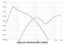
It's more complex than that. You need to get rid of the low bass bump and mid-hi dip if you want a normal crossover without the added eq. See attached. Since you say -3dB at 300Hz, are you looking for a two-way with 6dB per octave slopes and a Butterworth alignment? See the attached 260Hz at 12dB per octave. 6dB means removing even more components. It's a very simple circuit.
It's more complex than that. You need to get rid of the low bass bump and mid-hi dip if you want a normal crossover without the added eq. See attached. Since you say -3dB at 300Hz, are you looking for a two-way with 6dB per octave slopes and a Butterworth alignment? See the attached 260Hz at 12dB per octave. 6dB means removing even more components. It's a very simple circuit.
Attachments
Sebtdi
It's more complex than that. You need to get rid of the low bass bump and mid-hi dip if you want a normal crossover without the added eq. See attached. Since you say -3dB at 300Hz, are you looking for a two-way with 6dB per octave slopes and a Butterworth alignment? See the attached 260Hz at 12dB per octave. 6dB means removing even more components. It's a very simple circuit.
It's for an open baffle project bi-amp 12 " full range Lii F-12 drivers with 15" Eminence Alpha woofers. I was playing with mini-DSP 2x4 settings by ear all afternoon and settled with a 300 Hz crossover point @ 12dB/Octave Linkwitz curves with a 1200 Hz high-pass cut off frequency for the woofers - simple and sounds decent with good bass in my room acoustics.
I just want know what components values are needed to build the ACN without a lot of hours on software modelling/ EQ
sebtdi:
Here you go.
Thanks.
How do you fix the 120" Hz High-pass frequency?
Thanks.
How do you fix the 120" Hz High-pass frequency?
Sorry, I mean the 1,200 Hz High pass cut-off for the LF
sebtdi:
Here you go.
Hello
I have a few more noobies questions / clarifications -
1- What is the High Pass cut-off frequency for this design? trying here to match the frequency of the F-15 full range around 60-80 Hz
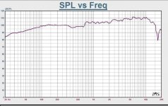
2- The frequency response of the Eminence A-15 shows a bump after 1,200 Hz and a sharp decline after 2,000 Hz - therefore selected Low Pass cut-off at 1,200 hz
3- Do these values eliminate the ACN low bass bump and mid-hi dip as per above graph? The digital DSP only shows smooth curves
4- Or, would the plain stock ACN build at 600 Hz -8 dB sound bad with this Open Baffle set-up? I have not tried these higher XO settings with the mini-DSP / EQ. The highest setting I played with DSP was 400 Hz and found the full range Lii F-12 was loosing its focus and blending too much with the Eminence Alpha's lows. 300 Hz was the sweet spot for my room.
Thank you
Attachments

Last edited:
Thinking more about your OB setup, it seems keeping the LX Mini LO OUT Hi Pass section that includes a bump at 50Hz with rolloff below that point might be of benefit.
1200Hz rolloff for LO OUT feeding the 15" woofer is not needed as it is many dB down by the time you get to that frequency. Maybe the attached will clarify things. I have included a schematic and the output plot curves. You use the values shown and bypass only the HI OUT HI EQ section, which is not needed. You do not even need to stuff & solder parts in that section.
1200Hz rolloff for LO OUT feeding the 15" woofer is not needed as it is many dB down by the time you get to that frequency. Maybe the attached will clarify things. I have included a schematic and the output plot curves. You use the values shown and bypass only the HI OUT HI EQ section, which is not needed. You do not even need to stuff & solder parts in that section.
Attachments
Yes.
One way to isolate the jumper from the rest of the circuit is to not install the parts in the EQ section (except for C10/12 and R44/46) and run the jumper from the input pad side of the R23/24 resistor location (which is connected by a trace to C10/12 negative) over to the output pad side of the C22/24 location (which is connected by a trace to the input side of R44/46).
Alternatively, you can leave the C10/12 capacitor negative lead uninstalled in the board and air wire the connection to the jumper wire. Leave the input lead of resistor R44/46 uninstalled in the board and air wire connect that end of the jumper wire.
Excellent!
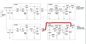
What is C29 10uF standalone for on the left LO pass? It's on First Watt schematics but not on your modeling.
What is C29 10uF standalone for on the left LO pass? It's on First Watt schematics but not on your modeling.
I do not see a C29 on the schematic or the board layout.
In red
Attachments
That appears to be a power supply bypass cap. It is shown in the PCB layout but not in either the main schematic or the power supply schematic. Probably added during board design but after the schematics were drawn. It is there to reduce potential noise and does not affect the filter frequency response.
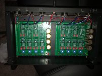
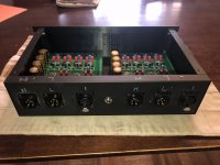
balanced crossover project completed!
All done and tested - more or leas 5% tolerance between boards, good enough as Papa said
Hardest part was the custom rear panel to fit 6 XLR mounts - a pita to drill all the large holes to size
**Special thanks to avdesignguru for his help with the custom crossover point and filters design
All done and tested - more or leas 5% tolerance between boards, good enough as Papa said
Hardest part was the custom rear panel to fit 6 XLR mounts - a pita to drill all the large holes to size
**Special thanks to avdesignguru for his help with the custom crossover point and filters design
Attachments
That appears to be a power supply bypass cap. It is shown in the PCB layout but not in either the main schematic or the power supply schematic. Probably added during board design but after the schematics were drawn. It is there to reduce potential noise and does not affect the filter frequency response.
Do you know how to further attenuate the volume of low pass? The stock values for P1-4 trim potentiometers are 25K. The maximum I can dial is 12K and would need more to balance between the two amplifiers.
Should I change the Bourns trim pots to 50K units to get a larger attenuation range ?
sebtdi:
I'm not sure what your problem is. Your statement "The maximum I can dial is 12K" does not make any sense. Theoretically, if you turn both the positive and the negative signal input trim pots associated with one of your balanced low out channels all the way down (P1 and P3), both the pot wipers will be at ground and no signal should be passing through the low pass circuit to the output.
I'm not sure what your problem is. Your statement "The maximum I can dial is 12K" does not make any sense. Theoretically, if you turn both the positive and the negative signal input trim pots associated with one of your balanced low out channels all the way down (P1 and P3), both the pot wipers will be at ground and no signal should be passing through the low pass circuit to the output.
That said, you may find things sound better with the crossover input pots all the way up and adding an attenuator to your power amplifier input,
All I want to do is attenuate the input to the crossover for the low related to the high at 10K. My class D amp has a lot of gain compared with the Aleph J for the highs. It's too boomy. The maximum range of the Bourns wiper is 12K.
As per Nelson's manual:
If you are running amplifiers all with the same gain, as originally set up for DSP,
then you can set the level pots on maximum. You are free to adjust the levels
from there, but best performance is obtained when either the low pass or high
pass are set at maximum and the other adjusted relative to it.
The crossover has a nominal 10 Kohm input impedance, and a nominal 200
ohm output impedance. It is very happy driving loads from 10 Kohm and up.
- Home
- Amplifiers
- Pass Labs
- LX-mini Crossover Article