The filters you point to are mostly inverters, so you have to reconfigure the
filters for unity gain buffers. This is do-able, if tedious.

filters for unity gain buffers. This is do-able, if tedious.

Hi, I am setting the trim pots of my Lx-mini crossover. I am using balanced inputs/outputs and have the crossover wired as such. When adjusting the trim pots, should I keep them both in the middle to give each side of the balanced input 11.9K ohms input impedance? I am using a Yamaha Cx-A5200 preamplifier to drive the balanced input. From reading the article, I'd like to minimize the trim pot for best performance. I just don't know what the Yamaha pre-amp can be expected to drive.
Also, should I trim the pot CW or CCW to minimize the impedance? Towards pin 1 or towards pin 3 of the trim pot?
Also, should I trim the pot CW or CCW to minimize the impedance? Towards pin 1 or towards pin 3 of the trim pot?
Nevermind, using the CW and W test-points on the board, I have zero ohms. This corresponds to turning the pot CW all the way. This should maximize the input signal to the crossover.
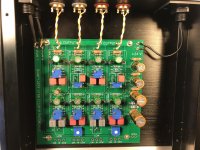
Here is how I made my notch filter. I did not have to modify the PCB, only be creative when installing the components.
Shouldn’t the notch be on the low pass side?
My high frequency driver has a peak that I wanted to remove at about 2.1 kHz, so the notch filter is in the high pass side.
Ahh, I understand. But doesn’t the circuit as designed already have a notch filter?
Please excuse my ignorance.
Please excuse my ignorance.
Here is how I made my notch filter. I did not have to modify the PCB, only be creative when installing the components.
Here is the one on the board.
Attachments

Last edited:
I am using this cross-over for a different speaker system than the LX-mini, so the original design was modified. My notch filter works over a narrower frequency range.Ahh, I understand. But doesn’t the circuit as designed already have a notch filter?
Please excuse my ignorance.
Hi there,
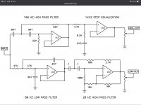
I need some help with a modification that I want to do on my lx mini crossover. I want to modify the hi-out notch section to make it behave like the 1khz step equalization that Nelson use in the Slot loaded open baffle project. He use the B5 I think to do that. You can see the equivalent schematic in the first image and Its on page 8 of this document: http://www.firstwatt.com/pdf/art_slob.pdf
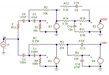
I’ve come up with a simulation in micro cap that seem to work. If someone could certify that it will work that would be great. You can see in the second image that I have left out R12 and C15 and readjust the values for R11 R14 C16. I’m just not sure about R10. In the simulation there’s no difference if I make it 0 or 18k2.. What is the purpose of R10?
Thank you!
Hubert
I need some help with a modification that I want to do on my lx mini crossover. I want to modify the hi-out notch section to make it behave like the 1khz step equalization that Nelson use in the Slot loaded open baffle project. He use the B5 I think to do that. You can see the equivalent schematic in the first image and Its on page 8 of this document: http://www.firstwatt.com/pdf/art_slob.pdf
I’ve come up with a simulation in micro cap that seem to work. If someone could certify that it will work that would be great. You can see in the second image that I have left out R12 and C15 and readjust the values for R11 R14 C16. I’m just not sure about R10. In the simulation there’s no difference if I make it 0 or 18k2.. What is the purpose of R10?
Thank you!
Hubert
Attachments
Switching from DSP to ASP...wiring question
After a long delay, I finally finished my ASP kit from the DIYAudio store for the LXMinis. I seem to remember that when one does this, the speaker wiring to the tweeter/midrange (upper) speaker needs to be reversed to keep that speaker and the woofer in phase when one switches from the MiniDSP.
I can’t see that in the build guide or the original Nelson Pass article, or by searching this thread, but is that the case?
I found this at the OPLUG forum—the phase to the upper driver does need to be reversed.
Last edited:
On page 4 of the lx-mini crossover article :
« The above curve also shows the response of both with the speaker drivers wired in-phase, where ideally they should have a deep null at the crossover point, a good indicator that the phases are identical at the frequency in normal use.
This reminds me to mention that there are no phase inversion circuits in this crossover, only unity gain discrete Jfet buffers without feedback. This means that with this crossover you have to invert the phase of the mid-tweeter, probably in the speaker wiring between the amp and the mid-tweeter, otherwise you will be listening to that big deep dip. »
😉
There it is. Thanks, Ylab! I had that printed and in my hand and couldn’t find it...right in front of me.
Sounds fantastic!
Sounds fantastic!
Hi everyone,
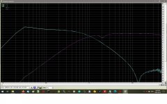
I've been testing the frequency response of my newly finished lx-mini and i have some strange behavior on both left and right low-out. Seem like I have a notch filter instead of a lo-pass 😕
Appart from the fact that i have replaced some resistor to make it ajustable, its exactly like the original. R9-R12 and R31-34 are mounted on the underside to give some space for the trimpots.
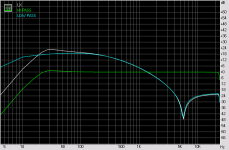
Green curve is the response at the output of the first stage (hi-pass). Looking clean, no notch. Blue is the response on the second stage (lowpass). So the notch seem to come from that part. White is the total reponse.
Does anyone have an idea of how i'm ending up with this? Ihave double check every value on the board and everything is ok. Voltage are ok too.
Any help would be greatly appreciated!
Hubert
I've been testing the frequency response of my newly finished lx-mini and i have some strange behavior on both left and right low-out. Seem like I have a notch filter instead of a lo-pass 😕
Appart from the fact that i have replaced some resistor to make it ajustable, its exactly like the original. R9-R12 and R31-34 are mounted on the underside to give some space for the trimpots.
Green curve is the response at the output of the first stage (hi-pass). Looking clean, no notch. Blue is the response on the second stage (lowpass). So the notch seem to come from that part. White is the total reponse.
Does anyone have an idea of how i'm ending up with this? Ihave double check every value on the board and everything is ok. Voltage are ok too.
Any help would be greatly appreciated!
Hubert
Attachments
Last edited:
Did you reverse the speaker leads to the mid-tweeter speaker? That is the difference vs MiniDSP
Those frequency response are taken directly at the LOW-OUT output of the crossover. So the notch is not a cancellation between two drivers.
I’m talking about the hi-pass and Lo-pass section of the LOW-OUT side of the circuit. They are identified on the board as such. Sorry for the confusion!
I’m talking about the hi-pass and Lo-pass section of the LOW-OUT side of the circuit. They are identified on the board as such. Sorry for the confusion!
Papa's published Ap response graphs only go to -20. The rise in response you show starting at about 6KHz and -48dB rising to -24dB may actually be normal. I doubt that it would be audible, given the falling response of the woofer at those frequencies.
Papa's published Ap response graphs only go to -20. The rise in response you show starting at about 6KHz and -48dB rising to -24dB may actually be normal. I doubt that it would be audible, given the falling response of the woofer at those frequencies.
Yeah maybe you are right. I have tested it on a woofer and everything seems ok. The simulation in micro cap don’t show this kind of behaviour though. If someone else could confirm that this is normal behaviour from the low pass section that would be great !
Hubert
- Home
- Amplifiers
- Pass Labs
- LX-mini Crossover Article