

It's extremely close. I had the M2 waveguides for a while and they looked just like that.
The interesting question is if this type of throat allows a wider angle than a standard OS-SE waveguide without sacrificing smoothness or if it's just to make the product look high-tech.
Personally, I enjoyed the wider pattern of the M2 vs typical 90 deg horns. They also had more consistent FR in the listening window than the typical OS and SEOS waveguides I had utilized up to that point. That was probably more a function of the gradual termination of the mouth as you have shown several times.
OK, here's my refined model (you need Ath 4.7.1). Anyone can easily adapt it for a different size, throat diameter, etc.
It could be improved further I think.
It could be improved further I think.
Code:
; Ath (4.7.1) - JBL M2 clone
Throat.Diameter = 36
Throat.Profile = 1
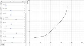
Coverage.Angle = 62 - 10*sin(p)^2 - 10*sin(2*(p+pi/4))^4
Slot.Length = 45 - 42*sin(2*p)^4
Length = 150
OS.k = 0.9
Term.s = 0.9
Term.n = 3 + 5*sin(2*p)^2
Term.q = 0.996
Morph.TargetShape = 1
Morph.CornerRadius = 8
; -------------------------------------------------------
Mesh.AngularSegments = 100
Mesh.LengthSegments = 32
Mesh.CornerSegments = 4
Mesh.ThroatResolution = 3
Mesh.MouthResolution = 10
; -------------------------------------------------------
ABEC.SimType = 1
ABEC.f1 = 500 ; [Hz]
ABEC.f2 = 10000 ; [Hz]
ABEC.NumFrequencies = 20
ABEC.MeshFrequency = 1000 ; [Hz]
ABEC.Polars:SPL_H = {
MapAngleRange = 0,90,19
NormAngle = 10
Distance = 3 ; [m]
Offset = 155
}
ABEC.Polars:SPL_V = {
MapAngleRange = 0,90,19
NormAngle = 10
Distance = 3 ; [m]
Inclination = 90
Offset = 155
}
; -------------------------------------------------------
Output.STL = 1
Output.ABECProject = 1Attachments

Last edited:
That's a tough one. From the data I have to believe that every single frequency response, measured at a single point in space, is actually minimum phase, no matter how strong reflections or diffractions are present. BUT, because of the 3D nature of the problem, it may not be correctable with an inverse filter. It almost seems as if the whole concept of minimum phase was not well defined for an acoustic problem like this.
- After all, if minimum phase represents the minimum delay for a given amplitude response, then I guess it holds even for a reflection. What's the minimum phase impulse response corresponding to a comb filter? Isn't it a delayed second impulse, i.e. a reflection?
I think the definition of a minimum phase has an implicit requirement that measurement destination is immaterial, that minimum phase holds for all destinations.
And yep, the 3D nature sure precludes that.😛
It may be true that an inverse filter can correct anything to one exact point in space...but i've come to doubt that, from measurements that seem to be chaotic (lack coherence) even in the best of measurement conditions.
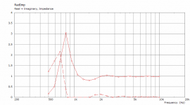
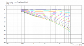
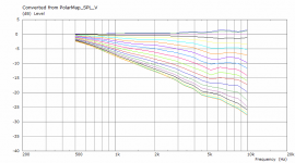
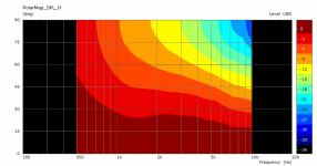
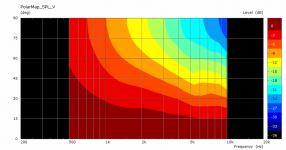
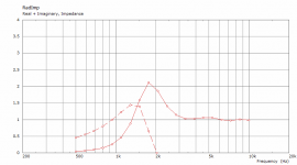
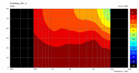
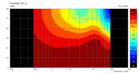
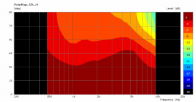
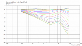
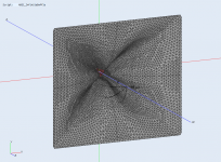
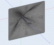
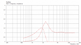
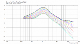
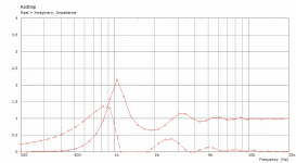
BEM results for the above model (M2 clone - probably a poor one 😛 )
- (H)orizontal, (V)ertical, (D)iagonal polars + throat impedance. Yeah, it's quite wide in H and V (up to some point).
Now I wonder how does the original looks like. It's also not so deep, IIRC.
- (H)orizontal, (V)ertical, (D)iagonal polars + throat impedance. Yeah, it's quite wide in H and V (up to some point).
Now I wonder how does the original looks like. It's also not so deep, IIRC.
Attachments


Last edited:


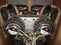
The cones must then breathe through 2 slots, each.
Tbh, I'm not convinced of the suitability of MEHs for hi-fi purpose (just my personal opinion), but there's a reason why Danley uses strictly conical horns.
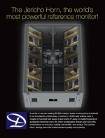
My favorite Danley is the Jericho J1, because that one doesn't sound like a giant horn. At least not at a distance of 5-50 meters.
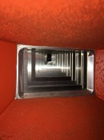
Jericho J7 has a diffraction slot:
It's extremely close. I had the M2 waveguides for a while and they looked just like that.
In the end you got rid of them?
Why?
OK, here's my refined model (you need Ath 4.7.1). Anyone can easily adapt it for a different size, throat diameter, etc.
It could be improved further I think.
Code:; Ath (4.7.1) - JBL M2 clone Throat.Diameter = 36 Throat.Profile = 1 Coverage.Angle = 62 - 10*sin(p)^2 - 10*sin(2*(p+pi/4))^4 Slot.Length = 45 - 42*sin(2*p)^4 Length = 150 OS.k = 0.9 Term.s = 0.9 Term.n = 3 + 5*sin(2*p)^2 Term.q = 0.996 Morph.TargetShape = 1 Morph.CornerRadius = 8 ; ------------------------------------------------------- Mesh.AngularSegments = 100 Mesh.LengthSegments = 32 Mesh.CornerSegments = 4 Mesh.ThroatResolution = 3 Mesh.MouthResolution = 10 ; ------------------------------------------------------- ABEC.SimType = 1 ABEC.f1 = 500 ; [Hz] ABEC.f2 = 10000 ; [Hz] ABEC.NumFrequencies = 20 ABEC.MeshFrequency = 1000 ; [Hz] ABEC.Polars:SPL_H = { MapAngleRange = 0,90,19 NormAngle = 10 Distance = 3 ; [m] Offset = 155 } ABEC.Polars:SPL_V = { MapAngleRange = 0,90,19 NormAngle = 10 Distance = 3 ; [m] Inclination = 90 Offset = 155 } ; ------------------------------------------------------- Output.STL = 1 Output.ABECProject = 1
If anyone else is trying to get this to work, here's what worked for me:
1) I downloaded the new version of ATH (4.7.1)
2) I installed the latest version of GMSH (Using the older version of GMSH didn't appear to be necessary)
3) I installed the latest version of Gnuplot
4) I installed ATH 4.7.0 and I replaced it's binary file with the binary from ATH 4.7.1
5) I modified "ath.cfg" to reflect where GMSH and Gnuplot are installed on my desktop computer
Sure, just install Ath 4.7.0 (as described in the manual) and then simply overwrite the file ath.exe with the 4.7.1 version. I somehow forgot to mention that.
Jericho J7 has a diffraction slot:
I'm not familiar with the J7.
It's the J1-94 that I've heard, at least on 8 occasions.
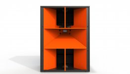
A stripped-down version of this concept might work at home. Forget the combiner-throat and the mids (keep a single BMS coaxial) and exchange the 18s for 15s or 12s.
Wrt drivers used, you'll end up with something that comes close to the BD systems, albeit with "synergy magic" and wider mid-high coverage.
Here's a video of the J1.
Attachments
Last edited:
Sure, no problem.
- It's not that easy, is it 🙂
- It's not that easy, is it 🙂
Code:
Throat.Diameter = 35
Throat.Profile = 1
Throat.Angle = 8
Coverage.Angle = 45
Slot.Length = 60
Length = 180
OS.k = 1
Term.s = 0.7
Term.n = 5
Term.q = 0.996

Mesh.AngularSegments = 16
Mesh.LengthSegments = 32

ABEC.SimType = 1
ABEC.SimProfile = 0
ABEC.f1 = 200 ; [Hz]
ABEC.f2 = 20000 ; [Hz]
ABEC.NumFrequencies = 40
ABEC.MeshFrequency = 36000 ; [Hz]

ABEC.Polars:SPL = {
  MapAngleRange = 0,90,19
  NormAngle = 10
  Distance = 3          ; [m]
  Offset = 185
}

Output.STL = 0
Output.ABECProject = 1
Attachments


Last edited:
The ripples... were to be expected. It "loads" pretty well and directivity is not terrible throughout the mid range.
In practice this would probably sound like a (big) dome tweeter on steroids.
In practice this would probably sound like a (big) dome tweeter on steroids.
Last edited:
- It's not that easy, is it 🙂
If only you knew 😉
After my studies I started to distance myself from the concept of competition.
In the foreseeable future it will become increasingly clear why.
Some pointers are included here.
Last edited:
- Home
- Loudspeakers
- Multi-Way
- Acoustic Horn Design – The Easy Way (Ath4)