It is possible to model the port and driver as a flat disc with a Lumped Element script for the bandpass chamber and that has been done before. It doesn't model the interaction between the chamber and the horn which is really the most important in my view.
This is how I would do it. Seems to me that you should be able to load some elements in the model with an impedance. To first order this would be a simple resonance. It would be interesting to see, but perhaps difficult to determine the values for this impedance. A Helmholtz resonator would be a first start.
I've always believed that these side ports should have an affect on the response, but I have not seen enough real data to tell either way. A sim would fit in this question nicely.
I might discount coupling of this port and the driver as important, but the waveguide interactions would be accounted for. That would be the point of the simulation.
A question about GD. Have we concluded that all waveguides and horns are minimum phase? Or just some shown here. Seems to me like that has been the underlying claim, but it doesn't seem right to me.
Last edited:
I've always believed that these side ports should have an affect on the response, but I have not seen enough real data to tell either way. A sim would fit in this question nicely.
There have been a few simulations of similar things done recently some links here with more information in the threads besides these specific posts for interested parties
2 way waveguide speaker build ABEC modelling
2 way waveguide speaker build ABEC modelling
2 way waveguide speaker build ABEC modelling
Full range line array for wall or corner placement
The lumped element simplification was done some time ago in one of the synergy threads
Synergy horn - 3d printing entry?
Last edited:
Thanks Fluid
-Ouch!! That's some pretty bad effects. Can't see why someone into Hi-Fi would do that. For pro, of course because its all about power.
-Ouch!! That's some pretty bad effects. Can't see why someone into Hi-Fi would do that. For pro, of course because its all about power.
An Ath generated waveguide can have excellent termination if the right parameters are used and so the issues the ports present are much more noticeable than they are in horn that already has bigger problems. I've run enough simulations of both to be confident in that part.
Whether that matters or not from an audibility perspective has not been tested enough to know for sure.
It seems worthwhile to try and find a way to minimize their impact without losing anything else.
That's very cool...i respect your findings.
I've found in other examples, like phase audibility for instance, it often takes excellence in other factors to let show its importance.
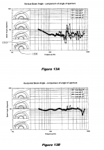
So trapezoidal ports resulted in the most consistent beamwidth. I find it surprising how many patents can be given out for what seems to me the same idea.
Material for the MEH masses.
Thx for that!
I wish for a centered, round hole comparison to those. Been my best luck so far.
It's back to square one, I guess.
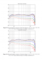
20 years ago, someone managed to cross a big OS waveguide at 450 Hz by using a high quality compression driver and primitive FIR techniques.
20 years ago, someone managed to cross a big OS waveguide at 450 Hz by using a high quality compression driver and primitive FIR techniques.
Attachments
-
Design of High-Quality Studio Loudspeakers using Digital Correction by Ulrich Horbach.pdf354.4 KB · Views: 142
-
 Design of High-Quality Studio Loudspeakers using Digital Correction by Ulrich Horbach_2.png273 KB · Views: 317
 -
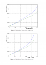 Design of High-Quality Studio Loudspeakers using Digital Correction by Ulrich Horbach_1.png134.4 KB · Views: 332
Last edited:
This is the exact reason horns interest me again. When the frequency response runs close to the power response, due to music content general spectrum, we are less likely to reach XMAX of the driver at the lower frequency end first in real life operation.When speaking of crossovers, one should always consider the final acoustical reponses (i.e. with all the electrical filtering in the crossover). There's absolutely no reason why should be the horn flat by itself down to the crossover frequency (or even below).
It really depends, My test articles all used an inverted dome tweeter with pretty similar directivity as data shown here.That's not constant directivity then.
That's a tough one. From the data I have to believe that every single frequency response, measured at a single point in space, is actually minimum phase, no matter how strong reflections or diffractions are present. BUT, because of the 3D nature of the problem, it may not be correctable with an inverse filter. It almost seems as if the whole concept of minimum phase was not well defined for an acoustic problem like this.A question about GD. Have we concluded that all waveguides and horns are minimum phase? Or just some shown here. Seems to me like that has been the underlying claim, but it doesn't seem right to me.
- After all, if minimum phase represents the minimum delay for a given amplitude response, then I guess it holds even for a reflection. What's the minimum phase impulse response corresponding to a comb filter? Isn't it a delayed second impulse, i.e. a reflection?
For those who would already like to start playing with this, here's a beta release: ATH - Advanced Transition Horns
What's new is the "Slot.Length" parameter. Attached is a sample project script. Don't try to make it free standing, that doesn't work yet, as some other things. But it can be simulated in an infinite baffle without any problems, as shown before. This feature allows to create some crazy stuff, be careful.
What's new is the "Slot.Length" parameter. Attached is a sample project script. Don't try to make it free standing, that doesn't work yet, as some other things. But it can be simulated in an infinite baffle without any problems, as shown before. This feature allows to create some crazy stuff, be careful.
Attachments
HornResp filter Wizard wont let me see above 1000hz anyway
Double-click on the "Frequency (hertz)" label to change the frequency range from 10-2000Hz to 100-20000Hz.
Attachments

Isn’t minimum phase defined as single input single output? If we include reflections, it means single input multiple output unless you are looking at the room as the system. If the system under evaluation is the driver and horn, then room reflections would not be included because it is the response of the driver/horn plus room.That's a tough one. From the data I have to believe that every single frequency response, measured at a single point in space, is actually minimum phase, no matter how strong reflections or diffractions are present. BUT, because of the 3D nature of the problem, it may not be correctable with an inverse filter. It almost seems as if the whole concept of minimum phase was not well defined for an acoustic problem like this.
- After all, if minimum phase represents the minimum delay for a given amplitude response, then I guess it holds even for a reflection. What's the minimum phase impulse response corresponding to a comb filter? Isn't it a delayed second impulse, i.e. a reflection?
Reflections can happen within the horn. The point is that the measured frequency response (at any single point), including these reflections, will most probably be minimum phase.
I'm not talking about the room, which we know is not minimum phase in the modal range, at least at some frequencies, but why is that (and not elsewhere), remains a mystery to me.
I'm not talking about the room, which we know is not minimum phase in the modal range, at least at some frequencies, but why is that (and not elsewhere), remains a mystery to me.
- Home
- Loudspeakers
- Multi-Way
- Acoustic Horn Design – The Easy Way (Ath4)