Would it work to use some kind of alternative source in place of mids? some dots on the walls, or a pulsating donut? 😀 got no clue, just a quick thought
Yeah, that could be done easily (you can make any single boundary element a source) but that's not the same thing as having a hole in the wall and a chamber behind it. That would be too easy...
Last edited:
Maybe some lumped model virtual mid dot? 🙂
Hmm I wonder what only mid playing polars look with one mid dot, or is it better with 2, 3 or 4?
Hmm I wonder what only mid playing polars look with one mid dot, or is it better with 2, 3 or 4?
Last edited:
When both mids and compression drivers are connected to amps or via a passive crossover, there is no problem. But I have heard stories about destroyed disconnected tweeters by midbass drivers in PA cabinets. But that is with much higher levels than home.
Maybe, as an approximation, but I'm not aware of such method.Maybe some lumped model virtual mid dot? 🙂
I would guess that as long as the wavelengths radiated by the mids are much larger than the slot diameter it will make very little difference.Hmm I wonder what the polars look with one mid dot only, or is it better with 2, 3 or 4?
While a slot doesn't get "overloaded" by a compression driver, I think the additional pressure of 2 cones may be too much, especially given the passband (low midrange).
Hi Ro, I always wondered that too.
But more and more, i now wonder what the compression limit is.
I know in the syns i've been building, that port holes totaling 1/10th Sd area work fine with no signs of distress, for anything 8" thru 12".
These ports are 5-7" from CD flange...so maybe it would be different if they ported closer to throat and into a smaller cross-sectional area, like a diffraction slot...dunno at all ...but beginning to doubt it whether it would matter.
^^Yeah I would imagine a separate model, a driver with front chamber and a hole in it, as the dot source. Could be used with any waveguide model easily without actually modeling the mid chamber to be part of the waveguide. I've got no idea if this is doable with the ABEC/AKABAK but I like to think everything is possible 🙂 and this wouldn't show the effect to the compression driver, mid holes would add diffraction?
Last edited:
It's definitely something to think about - to set the acoustic impedance of the "mid dot" as calculated in a separate (simple) model of the midrange chamber with the port. I'm no expert but maybe you have a great idea. I'm only not sure it's possible in ABEC, would have to check that.
Maybe it would but that's already way over my understanding of the physics involved.... and this wouldn't show the effect to the compression driver, mid holes would add diffraction?
That logic comes from trying to cross the mid drivers higher to use a smaller CD that can't go very low, in that case it has to be closer to work.I always thought that the closer are the entries/ports to the HF driver the better. It's not that simple?
The further out the ports are placed the less influence they have on the waveguides response but that places more demands on the CD and needs a lower crossover. That way seems a better choice to me.
Couldn't be the ports smaller when they are closer to the throat (higher pressure, lower velocity, lower losses)? I think of several small holes instead of one larger.
Could the mid taps work like a diffraction slot does?
If I remember Geddes mentioned zeroth order mode wouldn't mind porous waveguide walls, some time ago in this thread. Porous wall as mid taps?
Lots of interesting questions to simulate! 🙂
If I remember Geddes mentioned zeroth order mode wouldn't mind porous waveguide walls, some time ago in this thread. Porous wall as mid taps?
Lots of interesting questions to simulate! 🙂
That's how I envision it as well - I'd hope that several (very) small holes would not affect the response that much, perhaps.
But this is something I'd rather build/print than simulate.
But this is something I'd rather build/print than simulate.
It is possible to model the port and driver as a flat disc with a Lumped Element script for the bandpass chamber and that has been done before. It doesn't model the interaction between the chamber and the horn which is really the most important in my view.^^Yeah I would imagine a separate model, a driver with front chamber and a hole in it, as the dot source. Could be used with any waveguide model easily without actually modeling the mid chamber to be part of the waveguide. I've got no idea if this is doable with the ABEC/AKABAK but I like to think everything is possible 🙂 and this wouldn't show the effect to the compression driver, mid holes would add diffraction?
There is a commercial version of that which seems to work quite well and hold with the theory. They also chose to build rather than simulate, the simulation would be worthwhile on a small model to get the basics right but beyond that a printed prototype and measurement makes more sense. The model would get out of control quickly with the detail needed.That's how I envision it as well - I'd hope that several (very) small holes would not affect the response that much, perhaps.
But this is something I'd rather build/print than simulate.
COHERENT MIDRANGE INTEGRATOR (CMI)
I always thought that the closer are the entries/ports to the HF driver the better. It's not that simple?
As long as you don't want any efficiency gains, ie true horn loading, then yep, i think the closer the better. But efficiency is a pretty huge plus....
Also the one caveat already mentioned, the closer the ports are to throat the more disruptive they are reputed to be to the CD.
I say reputed because my testing keeps coming back to, that mouth termination issues cause much greater adverse effects on CD patterns.
No, my experience with 3D printing is exactly zero.
Although I have a friend who works for a 3D printer manufacturer and he suggested playing with his printer.
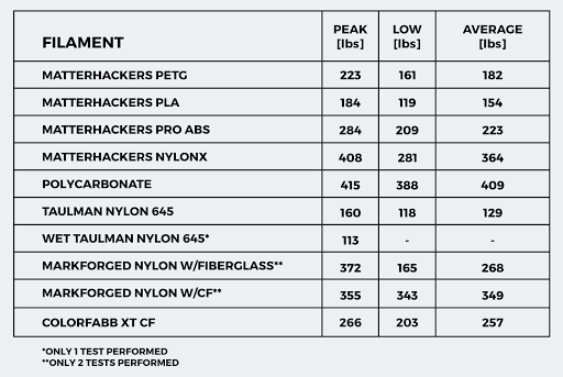
I believe their polycarbonate filament is available at cost price.
When I looked into 3d print materials I came to the conclusion that PETG was the best due to being the one filament (at that time) with the lowest shrinkage/warpage...that field is advancing so fast I wouldn't be able to say whats on the table now but PETG is better than PC from what I can tell at least...
Last edited:
An Ath generated waveguide can have excellent termination if the right parameters are used and so the issues the ports present are much more noticeable than they are in horn that already has bigger problems. I've run enough simulations of both to be confident in that part.Also the one caveat already mentioned, the closer the ports are to throat the more disruptive they are reputed to be to the CD.
I say reputed because my testing keeps coming back to, that mouth termination issues cause much greater adverse effects on CD patterns.
Whether that matters or not from an audibility perspective has not been tested enough to know for sure.
It seems worthwhile to try and find a way to minimize their impact without losing anything else.
Hi Ro, I always wondered that too.
But more and more, i now wonder what the compression limit is.
I know in the syns i've been building, that port holes totaling 1/10th Sd area work fine with no signs of distress, for anything 8" thru 12".
These ports are 5-7" from CD flange...so maybe it would be different if they ported closer to throat and into a smaller cross-sectional area, like a diffraction slot...dunno at all ...but beginning to doubt it whether it would matter.
Maybe you're right, Mark.
There are methods of calculating horn throat pressure which have been discussed in other threads. A few members have turned P. Audio PH-2380 and PH-4525 horns into MEHs.
In my way of thinking there should be unwanted interferences, depending on the size of the cone. If only because the cross sectional area of a slot is much smaller compared to a conical horn, which probably also adversely affects the passband behavior of the cones, unless they're tiny.
When I looked into 3d print materials I came to the conclusion that PETG was the best due to being the one filament (at that time) with the lowest shrinkage/warpage...that field is advancing so fast I wouldn't be able to say whats on the table now but PETG is better than PC from what I can tell at least...
- Home
- Loudspeakers
- Multi-Way
- Acoustic Horn Design – The Easy Way (Ath4)