I thought about attaching a pointer to a screwdriver and making a dial that attached to a trimmer so I could record the angle of a setting -- something like that. I do feel the need to be able to return to previous good setting.
Sorry. I misread your earlier comment. I thought you were recommending the multi-turn and agree with your actual assessment. I'll stick with the original build recommendation.
Sorry if this has already been answered. How do I calculate a standard Linkwitz-Riley 24db high pass filter for 80hz? I have searched a few online calculators but when I enter the numbers into the Pass XO calculator, the curve and frequency appear incorrect.
Also, do I need to compensate for the pot adjustment range?
Thanks,
Billy
Also, do I need to compensate for the pot adjustment range?
Thanks,
Billy
Last edited:
From the PDF... "So far we have been pretty lucky - the formula for the C capacitor value of the 6, 12, and 18 dB/octave filters has been a pretty similar to C = 7000 / Freq, with C in nanoFarads (nF)"
So... C=7000/80 = 87.5nF and C2 = .5 x C = 43nF
This is likely totally wrong but your question hung out there for a while. I figure this would at least allow someone to tell me how wrong I am and get you a correct answer.
So... C=7000/80 = 87.5nF and C2 = .5 x C = 43nF
This is likely totally wrong but your question hung out there for a while. I figure this would at least allow someone to tell me how wrong I am and get you a correct answer.
Sorry if this has already been answered. How do I calculate a standard Linkwitz-Riley 24db high pass filter for 80hz? I have searched a few online calculators but when I enter the numbers into the Pass XO calculator, the curve and frequency appear incorrect.
Also, do I need to compensate for the pot adjustment range?
Thanks,
Billy
You can use this calculator, https://sound-au.com/software/esp-lr13.exe
From the PDF... "So far we have been pretty lucky - the formula for the C capacitor value of the 6, 12, and 18 dB/octave filters has been a pretty similar to C = 7000 / Freq, with C in nanoFarads (nF)"
So... C=7000/80 = 87.5nF and C2 = .5 x C = 43nF
This is likely totally wrong but your question hung out there for a while. I figure this would at least allow someone to tell me how wrong I am and get you a correct answer.
This is the recommended way to get the values of C and C/2. In practice you will probably buy the nearest available values and trust your target will be within the range of the trimer adjustments.
The other thing it says in the PDF for the 24 dB/octave filters is "the classic L-R alignment will result from the P2 potentiometers to be at around 1/2 the resistance of the other pots". (Meaning the P1 pots, as can be seen it the Micro-Cap model of a 4 pole L-R filter on the second to last page of the PDF -- Note that the P1 and P2 labels come from the first schematic in the PDF).
EDIT: For Billah. You don't say what other sims you tried and what values you tried, or how it's different from the Pass XO calculator results. Can you give an example
Last edited:
Just placed a parts order with Digikey for all my components. I purchased several sets of C, C2 caps to play with. I also purchased two pole terminal blocks to put in the spots on the PC Board where the C and C2 caps mount so I can swap them out instead of soldering them in to make center frequency adjustments. Also purchased extra 25K pots and 4.7k resistor to make the range change for 24 dB slope adjustment range extension if I want to go that way. Lots of options!
to bullitt5094 #707
Hello bullitt5094,
I have chosen 100nF amd 47nF for my 6-24XO-build for subwoofer use.
My target crossover frequency was around 80Hz.
Greets
Dirk 😀
Hello bullitt5094,
I have chosen 100nF amd 47nF for my 6-24XO-build for subwoofer use.
My target crossover frequency was around 80Hz.
Greets
Dirk 😀
That seems correct to me, but the real experts will chime in if it isn't, I hope. I am learner, not one of the teachers on this thread. And to the experts... Thanks!
I still wonder if there is any way to measure a voltage anywhere on the board that will give you an idea of the current set-point of an output. The positioning of the POT is a clue, but it would be nice to have something more exact and replicate-able.
I still wonder if there is any way to measure a voltage anywhere on the board that will give you an idea of the current set-point of an output. The positioning of the POT is a clue, but it would be nice to have something more exact and replicate-able.
You can measure the resistance value of the trimers. There was some discussion of that around post #636.
If you want to measure the frequency response or the xover (and you want to climb another learning curve), I've used the free program REW and a audio interface on my laptop. One good series of videos on this is here: Measuring Gear With Room Eq Wizard - YouTube
--Frank, not an expert either...
24 db low pass & linkwitz transform?
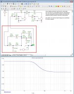
Allright, I love this tool and all its options! So I decided to educate/read some more on active (analog) crossovers. My aim is to create another board but a bit more tailored to my speakers. I started with microcap and replicating my low pass as it is currently in my system, a 24 low pass at 435hz, all good it seems:

Then I tried to add a linkwitz transform circuit, starting in Microcap:

So basically I just put in the schematic from Linkwitz. I am not so sure about the orientation of the opamp although the output in the graph is correct (11db gain as calculated). Where I am currently stuck is that I think that the opamp in the linkwitz circuit provides gain. Also I am not sure if this would work at all with the unity gain operating J113’s?
My question to the experts out here is whether it is possible to apply the Linkwitz Transform in the same 6-24 circuit using J113’s instead of the op amp?
Allright, I love this tool and all its options! So I decided to educate/read some more on active (analog) crossovers. My aim is to create another board but a bit more tailored to my speakers. I started with microcap and replicating my low pass as it is currently in my system, a 24 low pass at 435hz, all good it seems:
Then I tried to add a linkwitz transform circuit, starting in Microcap:
So basically I just put in the schematic from Linkwitz. I am not so sure about the orientation of the opamp although the output in the graph is correct (11db gain as calculated). Where I am currently stuck is that I think that the opamp in the linkwitz circuit provides gain. Also I am not sure if this would work at all with the unity gain operating J113’s?
My question to the experts out here is whether it is possible to apply the Linkwitz Transform in the same 6-24 circuit using J113’s instead of the op amp?
Attachments

My question to the experts out here is whether it is possible to apply the Linkwitz Transform in the same 6-24 circuit using J113’s instead of the op amp?
I'm not an expert but I do hack around some... and like you I learn by jumping into deep waters
The 6-24 uses JFETs as followers in active filter circuits where op amps are often used. It's a purist HiFi design by a master and it deserves careful study.
I don't totally understand the Linkwitz transform circuit but it seems to do complex things with both phase and frequency response, and some of the magic is happening in the negative feedback loop of the op amp. This circuit could be duplicated with transistors but it will be more complicated than the 6-24.
Last edited:
Thanks, I am in doubt if I will overcomplicate things in trying to add this circuitry. I am stuck at the moment😛
But as I am making the boards anyway, I like to explore additional functionality. In the end this will determine whether I will go sealed or ported for my cabinets.
If it turns out to be too complicated I might try a separate board with the regular opamp and dual rail PSU.
For anyone wanting to mess around with the microcap file I attached it. Do note: one is the 24db low pass and the other one has added the (most likely incorrect) linkwitz circuit. Based on these file it should be quite easy to add the high pass part of the circuit🙂
Attachments
My question to the experts out here is whether it is possible to apply the Linkwitz Transform in the same 6-24 circuit using J113’s instead of the op amp?
You are referring to the Linkwitz-Riley filters? They are do-able with
buffers - I seem to recall an LR example in the article for 24 dB/oct slopes.
I have been using LR 24db/oct happily for a while now with my original 6-24 board 🙂. This is the circuit I am referring to:

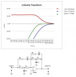
The transform circuit is 12 dB/oct highpass equalization and should allow me to take a driver in a sealed enclosure that has an Fc and Qtc for that enclosure and lets me "transform" or simulate a new Fc and Qtc for that driver in that enclosure.
Active Filters
In my example I have calculated the resistor and cap values (in spreadsheet floating around) to provide a 11db gain (red line in graph).
Attachments
Some of the best bass I've ever hear came from 18 inch woofers in comparatively small boxes employing a Linkwitz transform filter. 🙂 Watch your excursion.
"Linkwitz Circuit" Equalizes a Closed B - Maxim Integrated
"Linkwitz Circuit" Equalizes a Closed B - Maxim Integrated
Last edited:
I have 15 inch woofers and excursion should be within xmax (or Xlim for that matter) with my limited spl requirements. Good to hear you liked it! More motivation for me to try it out.
It looks like the op amp route is the way to go. I will have to provide for a bypass so I can eliminate the op amp circuit from this elegant circuit if it ends up not to my liking after all.
Best,
Robin
It looks like the op amp route is the way to go. I will have to provide for a bypass so I can eliminate the op amp circuit from this elegant circuit if it ends up not to my liking after all.
Best,
Robin
I would propose opamp circuitry for the bass part and JFETs for the rest. I doubt you will hear a difference in that frequency range. But for the part above say 80Hz use JFET circuitry.
This is the recommended way to get the values of C and C/2. In practice you will probably buy the nearest available values and trust your target will be within the range of the trimer adjustments.
The other thing it says in the PDF for the 24 dB/octave filters is "the classic L-R alignment will result from the P2 potentiometers to be at around 1/2 the resistance of the other pots". (Meaning the P1 pots, as can be seen it the Micro-Cap model of a 4 pole L-R filter on the second to last page of the PDF -- Note that the P1 and P2 labels come from the first schematic in the PDF).
EDIT: For Billah. You don't say what other sims you tried and what values you tried, or how it's different from the Pass XO calculator results. Can you give an example
Attempting to post a picture of the Pass XO calculator for the values I guessed.
B4E80A34-B139-42FC-B9EA-AEF45028A037.jpeg
Looks like I’m dangerous enough to post a picture the wrong way.
Billy
Last edited:
- Home
- Amplifiers
- Pass Labs
- DIY biamp 6-24 crossover