Measuring individual harmonics' levels and then calculating them long hand is a PITA beyond the third harmonic and gets worse if you use a passive notch filter and take account of its attenuation effects on the 2nd and 3rd harmonics.
That's certainly true. I'm just pointing out that you can get a long way by eye-balling things. Then fiddle with the software when you need the precise number.
The THD will be dominated by the tallest harmonic if all the others are at least 6 dB down. "Certain limitations and restrictions apply", of course. This does assume that only a few harmonics creep up above the noise floor, for example.
I was trying to point out to previous posters that there is a little 'gotcha' there in my experience.
Good point.
Tom
IMO why hassling with Arta when REW directly shows distortion levels and determines the fundamental from FFT results, as Jan already mentioned. Only when the fundamental cannot be determined (e.g. with a deep notch filter) REW takes the currently generated frequency as the fundamental hint. That can be used for measuring performance of analog oscillators as we did e.g. in https://www.diyaudio.com/forums/equ...n-audio-range-oscillator-899.html#post6205254
Yes, its probably about time I looked at REW and/or Audiotester - just familiarity and laziness on my part. Maybe its time for a functional request to Ivo.
Cheers from a somewhat getting-chillier-by-the-minute UK
Mike
Cheers from a somewhat getting-chillier-by-the-minute UK
Mike
Unfortunately you will need to wait for a QA402, since the chips for the QA401 are not available.
I would strongly recommend DiAna DiAna DiAna, a software Distortion Analyzer for distortion measurement and analysis of low distortion oscillators. it can characterize and compensate for passive notch filters and it has the best analysis tools I have seen since the Shibasoku 725 analyser. You can see from the residual wave pretty clearly where to look for nonlinearities.
I would strongly recommend DiAna DiAna DiAna, a software Distortion Analyzer for distortion measurement and analysis of low distortion oscillators. it can characterize and compensate for passive notch filters and it has the best analysis tools I have seen since the Shibasoku 725 analyser. You can see from the residual wave pretty clearly where to look for nonlinearities.
With REW you can measure the notch first and use that as the "soundcard calibration" which undoes the notch in the display and calculations, so even when the notch is off in frequency this still does work.IMO why hassling with Arta when REW directly shows distortion levels and determines the fundamental from FFT results, as Jan already mentioned. Only when the fundamental cannot be determined (e.g. with a deep notch filter) REW takes the currently generated frequency as the fundamental hint. That can be used for measuring performance of analog oscillators as we did e.g. in https://www.diyaudio.com/forums/equ...n-audio-range-oscillator-899.html#post6205254
Hi again,
Thanks for the suggestions folks. Another project for the 'to do' list. 😀
Cheers,
Mike
Thanks for the suggestions folks. Another project for the 'to do' list. 😀
Cheers,
Mike
does anybody have experience with this Low-distortion Audio-range Oscillator or can provide insight about the circuit?
The stated THD 0.002%@1kHz is more than enough for me as I need it mostly for checking tube gear
The stated THD 0.002%@1kHz is more than enough for me as I need it mostly for checking tube gear
This is an interesting design and will probably suit your needs. It is not a very simple circuit, however. It uses two first-order all-pass filters to obtain the needed 180 degree phase shift at the oscillating frequency. This contrasts with a state variable oscillator that uses two integrators to achive the 180 degree phase shift and frequency-dependent elements. The all-pass sections provide no attenuation at frequencies above the oscillation frequency, while the integrators in the SVO provide 6 dB/octave each above the oscillating frequency.
Bottom line is that the SVO is no more complex in terms of number of op amps and probably performs better.
Cheers,
Bob
Bottom line is that the SVO is no more complex in terms of number of op amps and probably performs better.
Cheers,
Bob
does anybody have experience with this Low-distortion Audio-range Oscillator or can provide insight about the circuit?
The stated THD 0.002%@1kHz is more than enough for me as I need it mostly for checking tube gear
When investigating low distortion audio oscillators some time ago, I built both the Linsley Hood Wein Bridge Oscillator and the Rosen Phase Shift Oscillator.
These are both spot frequency generators. I chose 100Hz, 300Hz, 1kHz, 3kHz, 10kHz, 20kHz for both.
I built the Linsley Hood Wein Bridge Oscillator using LM4562 op amps and an RA53 thermistor.
I measured 0.003% distortion @ 1kHz using an HP3850A spectrum analyser and a passive notch filter.
The Rosen Phase Shift Oscillator also used an RA53 thermistor with NE5532 op amps. I measured 0.002% distortion @ 1kHz.
Both circuits are relatively simple and the results I obtained are pretty similar. Of course the thermistors are now hard to find - although you can often find them used in oscillators for sale on eBay.
If you want a low distortion oscillator that is adjustable over the full audio range rather than spot frequencies then you may be better off using a SVF Oscillator. I built one based on the HP8903A using LM4562 op amps with a sample & hold + FET for level control. The circuit is a lot more complex but there is no amplitude bounce and the distortion is very low over the full audio range.
Beware of buying cheap fake LM4562 op amps on eBay. I fell into that trap and it took me some time to figure out what was wrong.
Another thing to watch out for: When building an oscillator based on the Wein Bridge circuit, there are problems obtaining good quality matched dual-gang potentiometers.
If the two gangs do not match then you need more positive feedback to make sure the oscillator starts reliably over the full frequency range.
The extra feedback results in increased distortion. I've had problems even with good quality potentiometers from Bourns or Alps.
For this reason it's usually better to use spot frequencies using a switch and fixed resistors / capacitors.
Last edited:
lots of useful info Brian, thank you
Btw I eventually built the one in my link and it worked alright first time (surprise 🙂).
The frequencies are spot on and now I have to set my hands on a spectrum analyzer to confirm the THD level
Edit: I just now realized that the circuit I built is the one in the opening post from 2012 - what were the chances!
Last edited:
Oops, typo - I meant HP3580a spectrum analyser.
This has a dynamic range of 80dB so a notch filter is essential when measuring low levels of distortion. When calculating the THD, you need to take into account the attenuation of the low order harmonics by the notch filter and sum the contributions from each of the harmonics. The easiest way is to create a spreadsheet.
This has a dynamic range of 80dB so a notch filter is essential when measuring low levels of distortion. When calculating the THD, you need to take into account the attenuation of the low order harmonics by the notch filter and sum the contributions from each of the harmonics. The easiest way is to create a spreadsheet.
Low distortion capacitors?
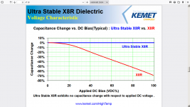
I just got a link from a colleague from my working days. The link claims very low voltage coefficient of capacitance. Should bode well for low distortion.
https://sh.kemet.com/Lists/FileStore/High Temp MLCC PTM 4.11.14.pdf
I just got a link from a colleague from my working days. The link claims very low voltage coefficient of capacitance. Should bode well for low distortion.
https://sh.kemet.com/Lists/FileStore/High Temp MLCC PTM 4.11.14.pdf
Actually, last year I have developed a temp control unit for the 4 caps that determined a low pass filter cut-off freq. Rock stable, with temp deviations below 0.01C.
Jan
Jan
The Voltage coefficient of the improved ceramic dielectric is interesting and important but that's still not a good material for a critical timing part.
Polystyrene would not need that level of temp control. And there are other options: Polystyrene Capacitors - What Happened to Polystyrene Film Capacitors?.
The resistors would also be an issue. Before crystal locked stuff designers were pretty skilled at mixing resistor and cap tempcos to cancel each other. I have one precision source with a thermistor in it to correct for frequency drift. It seems to hold OK to .1%.
- Home
- Design & Build
- Equipment & Tools
- Low-distortion Audio-range Oscillator