> This was never designed to be compete with the Colemans, it was designed to compete with the Tentlabs
Today is the 2nd time I have had to intervene in false (flat out wrong) comparisons you have made against my regulator.
> A second source for anything is always a good idea even if the replacement may not be up to scratch.
Is this a Mission Statement? 😀
Today is the 2nd time I have had to intervene in false (flat out wrong) comparisons you have made against my regulator.
> A second source for anything is always a good idea even if the replacement may not be up to scratch.
Is this a Mission Statement? 😀
Back to the design work.....
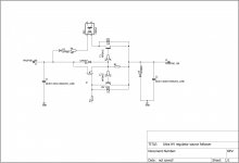
The arrangement for the negative supply voltages for the bias and the source follower:
We should probably decide on how high to set the bias voltage limit.
At 1100V on the anode, the grid bias range is probably around -140V; but we should allow for a margin, given the variability of the various Ulyanov and other branded GM70s known to exist, as well as the Copper versus Graphite versions.
If we (arbitrarily) set the limit to -180V, it should suffice.
-180V at the grid means that a DC-coupled source follower must swing more than double this in magnitude: say, -380V to +20V (if we entertain the idea of a little A2). This suggests that the supply voltage for the follower should be (say) -400V and +50V. The bias regulator could (in theory) run from -400V and give -185V to -110V output. But such a high input-to-output difference is unnecessarily stressful, and would degrade the performance. It is far better to use a centre-tapped transformer and generate -200V and -400V with one bridge rectifier, and stacked output capacitors. The +50 (50-70V) could be had from another winding on the same transformer.
Hey Rod,
Thank you, these were the number i was looking for...
Ok for the fact that the power supply needs double voltage for the source follower... But wow! I never thought in this fashion!
These days I didn't have the time to study Ale's source follower schematics, but yes your judgement sounds right...
So what secondaries do i need to tell to my winder? [emoji14]
+50v, +400v, +8v (i still use that for the small valves, following the original scheme, but perhaps it's the case to put this winding together with those of gm70 heaters, and keep this PT just for the bias)
I think you may be able to go for a voltage doubler from the same winding provided the bias winding isn't loaded to heavily by the source follower sinks. However you should tale care to specify electrolytic s that will hold up over time for the doubler part or this choice may come back to bite you in the rear. An extra winding is expensive. So its worth considering.
The heretic i am suggests another approach 😛 WE makes an off the shelf core for a flyback. https://www.we-online.com/catalog/datasheet/750343772.pdf
If you run the primary FET with the wimpy driver of the UC3843 you will get little in the way of pervasive noise, but you need to sink it quite well.(SK129-50 would suffice) A 100uH 10uF filter on the secondary side would keep out the main switching harmonics. And a couple of 1206 SMD beads would do the rest. Been there done that. You could even go as far as to use some of the new silicon carbide fets for those because those are said to produce less harmonics. (You need quite a high voltage device anyway because of the reflected voltage)
You could do the heretics a solid by putting a footprint for an opto with emitter and collector out. The Led would go over the pass device with a zener and resistor in series. This could then be used for a wide variety of purposes, one of which is to detect short circuits downstream* and interface this easily with digtal logic. Or to use a flyback as a preregulator😛
*By this i mean that most series regulator designs have some sort of current limit, or foldback mechanism, and if the output overloads the output voltage will sag and hence the voltage over the pass device will increase. I dont know about the headroom on your design but a 25 cents opto and a 10 cents resistor plus diode allows you to easily interface this with digital electronics.
Last edited:
We should probably wait for some thoughts and experience from Vincent and Kevin, about the operating points.
The -140 to -180V bias point are based on the idea that the Anode voltage should be 1100-1200V, for the best sound with GM-70s. Lower Va would give lower bias voltages - but I would think that constructors here will choose to go for the best possible sound.
The -140 to -180V bias point are based on the idea that the Anode voltage should be 1100-1200V, for the best sound with GM-70s. Lower Va would give lower bias voltages - but I would think that constructors here will choose to go for the best possible sound.
I had the idea to do SCR phase control to keep the voltage over the FET source follower in check, most people run chokes for the supply anyway. And nowadays chokes are cheap.
TDS10/250 - Toroidal Choke 10H 250mA DC - Shop Toroidy.pl
As far as the PSU goes: why not stack the high voltage on the source follower driver supply? That way you could use some surplus MKP caps on ebay right now. 40uF 1100V EPCOS are cheap now.
About that fet in the high voltage supplies. This part is much more durable there: https://cdn-reichelt.de/documents/datenblatt/A200/IXTK8N150L.pdf
If you add a simple source resistor plus BJT to create an overcurrent protection in the FET. Interface that with the phase controller with a Zener+ Opto and you can get away with much less heatsinking for the FET.
If you put a opto like a CNY64 over the source-drain like attached schematic you can get the loop to regulate away over current and over voltage.
I put a zener in there for normal operation and setting the voltage over the FET. Should overcurrent occur the transistor over the current sense resistor will override the zener.
Attachments
So, i was in mood to play....
i found this LTspice GM70 model:
Let's suppose the model is good.
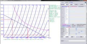
I loaded Vincent static points (1057 plate V, 90mA current) to discover the bias is around -105V.
Seems that to remain in A1 class we need 200Vpp (140V RMS), at 23W output.
Perhaps a little tight, but even the D3A in triode mode should output this voltage (fig.2) Am i wrong?
Even better should be th E186F, but all we want is to reduce the impedance that the driver output sees.
Please tell me if these numbers make sense to you, i'm new to this paint-kit tool.
Now, what I am completely missing, is Rod's statement:
why has to swing more than double?
that's consequent then.
question is, do we need three separate voltage sources ? One at -400, one at -200, one at +50/+70V ?
How does this work?
i found this LTspice GM70 model:
Code:
**** GM70 ** Advanced Grid Current **********************************
* Created on 11/03/2020 21:33 using paint_kit.jar 3.1
* [url=http://www.dmitrynizh.com/tubeparams_image.htm]Model Paint Tools: Trace Tube Parameters over Plate Curves, Interactively[/url]
* Plate Curves image file: gm70.png
* Data source link:
*----------------------------------------------------------------------------------
.SUBCKT GM70 1 2 3 ; Plate Grid Cathode
+ PARAMS: CCG=8P  CGP=4P CCP=1.9P
+ MU=8.022 KG1=7782.36 KP=163.03 KVB=31.44 VCT=9.1 EX=1.636
+ VGOFF=-0.93 IGA=0.00097 IGB=0.3 IGC=8 IGEX=2
* Vp_MAX=2000 Ip_MAX=300 Vg_step=20 Vg_start=0 Vg_count=13
* Rp=4000 Vg_ac=53.35 P_max=125 Vg_qui=-67.6 Vp_qui=630
* X_MIN=51 Y_MIN=54 X_SIZE=700 Y_SIZE=526 FSZ_X=1296 FSZ_Y=736 XYGrid=false
* showLoadLine=n showIp=y isDHT=n isPP=n isAsymPP=n showDissipLimit=y
* showIg1=y gridLevel2=y isInputSnapped=n
* XYProjections=n harmonicPlot=n dissipPlot=n
*----------------------------------------------------------------------------------
E1 7 0 VALUE={V(1,3)/KP*LOG(1+EXP(KP*(1/MU+(VCT+V(2,3))/SQRT(KVB+V(1,3)*V(1,3)))))}
RE1 7 0 1G  ; TO AVOID FLOATING NODES
G1 1 3 VALUE={(PWR(V(7),EX)+PWRS(V(7),EX))/KG1}
RCP 1 3 1G   ; TO AVOID FLOATING NODES
C1 2 3 {CCG} ; CATHODE-GRID
C2 2 1 {CGP} ; GRID=PLATE
C3 1 3 {CCP} ; CATHODE-PLATE
RE2 2 0 1G
EGC 8 0 VALUE={V(2,3)-VGOFF} ; POSITIVE GRID THRESHOLD
GG 2 3 VALUE={(IGA+IGB/(IGC+V(1,3)))*(MU/KG1)*(PWR(V(8),IGEX)+PWRS(V(8),IGEX))}
.ENDS
*$
Let's suppose the model is good.
I loaded Vincent static points (1057 plate V, 90mA current) to discover the bias is around -105V.
Seems that to remain in A1 class we need 200Vpp (140V RMS), at 23W output.
Perhaps a little tight, but even the D3A in triode mode should output this voltage (fig.2) Am i wrong?
Even better should be th E186F, but all we want is to reduce the impedance that the driver output sees.
Please tell me if these numbers make sense to you, i'm new to this paint-kit tool.
Now, what I am completely missing, is Rod's statement:
that a DC-coupled source follower must swing more than double this in magnitude: say, -380V to +20V (if we entertain the idea of a little A2).
why has to swing more than double?
This suggests that the supply voltage for the follower should be (say) -400V and +50V.
that's consequent then.
The bias regulator could (in theory) run from -400V and give -185V to -110V output. But such a high input-to-output difference is unnecessarily stressful, and would degrade the performance.
It is far better to use a centre-tapped transformer and generate -200V and -400V with one bridge rectifier, and stacked output capacitors. The +50 (50-70V) could be had from another winding on the same transformer.
question is, do we need three separate voltage sources ? One at -400, one at -200, one at +50/+70V ?
How does this work?
Attachments
and just for reference, this Ale Moglia's blog post about a very similar GM70 schematic, with source follower and gyrator:
GM-70 SE Amplifier – Bartola(R) Valves
and by looking at the scheme, i see now the source follower has a B+ of 25V, and a B- of -250V (same raw DC of bias supply), and Rod's bias reg gives -110V (starting from 0-250VDC)

GM-70 SE Amplifier – Bartola(R) Valves
You are not limited to the 6SF5 of course, you can use many other great triode (or pentode) drivers here. You just need to have enough headroom and gain to deliver effectively 200-220Vpp. Not many drivers can do this well at low distortion. If you don’t want to pursue the DHT route (e.g. an 801a/VT-25 with a 1:8 SUT) you can look into D3a, E810F as well as many others I have blogged around here:
and by looking at the scheme, i see now the source follower has a B+ of 25V, and a B- of -250V (same raw DC of bias supply), and Rod's bias reg gives -110V (starting from 0-250VDC)
Last edited:
> why has to swing more than double?
We need the driver stage to swing to the cut-off (Ia=0) and then to zero... But not just to zero, but a little higher, to allow for some A2 drive. Also, we don't want the driver to suddenly stop at 0V or the distortion at clipping will be more audible.
If the bias is really 105V or near to it, that would make it easier. But the data sheet curves show more grid voltage than that, and it's worth having some extra voltage because Ulyanov and Reflektor tubes are in general subject to wide sample to sample variation.
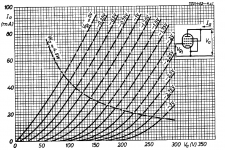
This is the Data sheet figure that I had assessed the nominal grid voltage from.
At 1100V and 90mA it indicates about -147V.
In reality, it might be somewhat different - perhaps the data sheet is from another manufacturer, or the internal geometry changed across the many years the GM-70 was in production.
It would be very helpful if anyone whose main amp has GM70s to comment on the range of real settings for the bias voltage.
Otherwise, using a nominal Raw DC voltage of -250V for the follower + bias will be one option - and since Vincent's schematic is marked with this value, it is likely to be safe.
Attachments
Hi Rod, i worked yesterday on that, give me a little time to upload the (final) schematic.
Yes, I'm willing to keep the bias at -110V, ca. 90mA.
Give to the source follower -270 +50V.
Yes, I'm willing to keep the bias at -110V, ca. 90mA.
Give to the source follower -270 +50V.
Last edited:
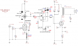
So friends, I elaborated the schematic, this should be my "freeze" result.
I ask you please to put en eye on that, you know electronics better than me for sure.
I wish to keep neg bias at -110V, as per Vincent's design, and many other designs I found on the web. Looks convenient.
Let the source follower then swing -110V +- 160V, resulting in -270V/+50V;
driver tube is biased with three Schottkyes C3D02060F, 0.85V each at 10mA.
Gyrator and SF schematics as follow, I would keep the drivers' B+ at 360V.
What do you think?
Now please, I need your help in designing a raw DC bias power supply for the given values (-270V, +50V, Rod's 110V out), with transformers' secondaries shared with the drivers' filaments (the 8VAC 3A = 24Va leg in Vincent's schematic.).
Attachments
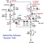
Hi Michelangelo
On the gyrator circuit, the LED (D4) isn't needed unless you want some visual indicator. If so, you will need R8 to be 220R for the idle current in your driver. Otherwise R8 serves as a protection to the MOSFETs in case you short the output of it. Best combination of cascoded FETs in my opinion is BSH111BK (or BSN20BK) and IXTP08N100D. Not sure why you added "x2" in the diagram as there is only one needed.
Source follower is ok, you will need a good set of heatsinks or mount them under the PCB to a chassis. The SF MOSFETs are plastic TO220 so their insulation is very handy. You will dissipate about 5W across the 2 MOSFETs.
For the raw PSU you can check the example on my 300B design here, albeit you will need to increase your secondary voltage if you want 270V raw. Do you know how to work with PSUD2?
300B SE Amplifier – Bartola(R) Valves

cheers
ALe
On the gyrator circuit, the LED (D4) isn't needed unless you want some visual indicator. If so, you will need R8 to be 220R for the idle current in your driver. Otherwise R8 serves as a protection to the MOSFETs in case you short the output of it. Best combination of cascoded FETs in my opinion is BSH111BK (or BSN20BK) and IXTP08N100D. Not sure why you added "x2" in the diagram as there is only one needed.
Source follower is ok, you will need a good set of heatsinks or mount them under the PCB to a chassis. The SF MOSFETs are plastic TO220 so their insulation is very handy. You will dissipate about 5W across the 2 MOSFETs.
For the raw PSU you can check the example on my 300B design here, albeit you will need to increase your secondary voltage if you want 270V raw. Do you know how to work with PSUD2?
300B SE Amplifier – Bartola(R) Valves
cheers
ALe
Thanks Ale,
yes I can work at a basic level with PSUD2, can't add sigle C or R stages though, and perhaps for the bias supply I'd like have two stabilized legs...
yes I can work at a basic level with PSUD2, can't add sigle C or R stages though, and perhaps for the bias supply I'd like have two stabilized legs...
Last edited:
It would be very helpful if anyone whose main amp has GM70s to comment on the range of real settings for the bias voltage.
I remember that there was a lot of variance between tubes, with copper/graphite being quite different.
I will try one of these days to open my amp and measure the bias voltage of a few different tubes.
So yesterday my first daughter was born, now the design of the stabilized bias -250/+50 is definitely on hold!
But will follow soon!
If you wish to make your design, would be appreciated!
Leading to clinic now!
But will follow soon!
If you wish to make your design, would be appreciated!
Leading to clinic now!
This is the Data sheet figure that I had assessed the nominal grid voltage from.
At 1100V and 90mA it indicates about -147V.
In reality, it might be somewhat different - perhaps the data sheet is from another manufacturer, or the internal geometry changed across the many years the GM-70 was in production.
It would be very helpful if anyone whose main amp has GM70s to comment on the range of real settings for the bias voltage.
Otherwise, using a nominal Raw DC voltage of -250V for the follower + bias will be one option - and since Vincent's schematic is marked with this value, it is likely to be safe.
My GM-70 v+ is 1050v@100ma, V bias somewhere between -100- -110 V, can check in the evening.
Memory is ....
Michelag: Congrats!
( memory is
Congratulations.
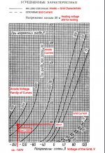
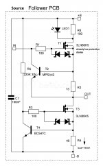
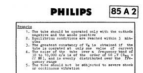
If you sink the Follower CCS current into the Unregulated supply (Which hardly matters for noise cause the CCS is high impedance), you can get away with a shunt out of two 85A2 set by a DN2540 cascode CCS for the grid bias. Simple and practically impossible to beat.
Philips Specifies a 60uV MAX noise figure per tube, if the supply feeding it is relatively low noise and the cascode impedance is >=100K total noise on the bias supply is never going to be above 170uV for -170V out, which to my knowledge is sub 1PPM.
See an excerpt from the Philips datasheet, its damm near impossible to beat. And is on par with the noise figure of one of the quitest references i know of: LT1021
Attachments
- Home
- Amplifiers
- Tubes / Valves
- Interesting GM70 scheme... Some questions on the PSU, who helps me please?