'Interesting' question!
The Atmel microcontroller has (only) 2 hardware PWM output for each timer/counter, hence it was straightforward to generate 2 phases with a fixed relationship. Going to 3 phases would require using a second timer/counter, which should be possible if the additional calculations can be squeezed into the time available for the interrupt service routine. I'd probably have to ditch the tachometer test tone generator to liberate its timer. Hardware wise, I'm sure a second board could be stacked and connected to run from an alternative output pin. The extra hardware solution shown above is an option, but I think it would be nice to do it in the processor if possible. I have some other projects on the go (and a job unfortunately!), but you never know what may happen on a rainy day.......
Thanks richb and thanks to ralphfcooke.
It would indeed be interesting to integrate the third phase into the project, if possible, rather than adding a board. So we will wait for a rainy day...
OK so despite it not raining at the moment I got curious......
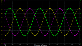
I had to save one of the traces as I only have a 2ch 'scope, but this is all 3 phases running simultaneously.
I have some work to do on storing the values to EEPROM and updating the control interface, but this is proof of concept at least 🙂
I had to save one of the traces as I only have a 2ch 'scope, but this is all 3 phases running simultaneously.
I have some work to do on storing the values to EEPROM and updating the control interface, but this is proof of concept at least 🙂
Attachments
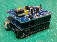
Here's the 3-phase 'stack'!Nice project !
The board is designed to work with 2 phase synchronous motors only. Is it possible to stack two pcb to drive a 3 phase BLDC motor (with the MA-3D board) ?
More by luck than judgement, it has worked out very straightforward to add a second board for the third phase - only the 'upper' channel is populated, with its input connected across to the re-purposed GEN output on pin10, and using low-profile or horizontally-mounted capacitors for clearance to the top board. The unused channel of the OPA2134 is connected with unity feedback to prevent any switching due to noise. The top board is the completely standard build as for a 2 phase generator.
It works as per the previously posted 3-phase output. I will produce a unified firmware that works for both 2 and 3 phase outputs and post here when available.
Attachments
Last edited:
Hello Richard,
Very well done and quickly. Do you still have boards available ? If so, I would like two.
Another question : if you completely remove the HA-06 after tuning, isn't it possible to add a small 7-segment LED display with a TM1637 board ? I find the bluetooth solution very modern and easy, but I would like to have a small display near the start button to check directly if the system is working well (for peace of mind).
Build guide and latest 2 or 3 phase firmware
Here is the latest firmware that supports 2 or 3 phase sinewave generation plus updated tuning interface, along with a build guide for the project covering the PCB build, firmware installation and interface, plus a BOM.
Here is the latest firmware that supports 2 or 3 phase sinewave generation plus updated tuning interface, along with a build guide for the project covering the PCB build, firmware installation and interface, plus a BOM.
Attachments
Last edited by a moderator:
Hi, thank you. I still have a few left from my initial batch, please PM me.Hello Richard,
Very well done and quickly. Do you still have boards available ? If so, I would like two.
Another question : if you completely remove the HA-06 after tuning, isn't it possible to add a small 7-segment LED display with a TM1637 board ? I find the bluetooth solution very modern and easy, but I would like to have a small display near the start button to check directly if the system is working well (for peace of mind).
Yes it should be possible; the tachometer was integrated into the sinewave generator as an 'add-on', having previously been using a stand-alone tachometer with its own display. When integrated, as the Arduino has only one hardware serial port, I kept this for the BT interface. There are many other display options that could be added, but for this project I currently don't wish to go down that route; as the firmware is freely shared you're welcome to do your own development for other features 🙂
Many thank to Richard for sharing this great project.
I am in the process of building and I have just received the HC-06 Bluetooth module and testing it found it will not connect to my iphone.
Connected to an old Android phone ok.
Anybody else have the same problem?
I am in the process of building and I have just received the HC-06 Bluetooth module and testing it found it will not connect to my iphone.
Connected to an old Android phone ok.
Anybody else have the same problem?
Hi Richard.
My coding skills are not fantastic so I was wondering if you could point me in the right direction to add the ability to modify the amplitude with a max & min setting as on the Pyramids SG4 controller?
My coding skills are not fantastic so I was wondering if you could point me in the right direction to add the ability to modify the amplitude with a max & min setting as on the Pyramids SG4 controller?
Hi, it doesn't have a variable amplitude feature as is uses a fixed amplitude sinewave lookup table, sorry!Hi Richard.
My coding skills are not fantastic so I was wondering if you could point me in the right direction to add the ability to modify the amplitude with a max & min setting as on the Pyramids SG4 controller?
Last edited:
Hello Richard,
The PCB is arrived today.
Thank you very much.
I hope I'll find the time to build the generator quickly.
The PCB is arrived today.
Thank you very much.
I hope I'll find the time to build the generator quickly.
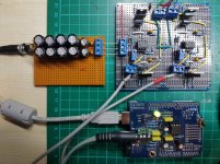
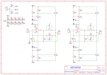
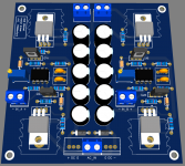
I've put together an easy to build amplifier suitable for driving my 24v Rega motor from the sinewave generator, and it works very nicely. Shown here is a 2 channel prototype, powered from the standard Rega AC adapter.
There are of course many options for this, but if it's of any interest then details are in this thread.
There are of course many options for this, but if it's of any interest then details are in this thread.
Attachments
I am interested in one of the PCB. Would be nice to get everything inside one box. I would prefer an smps supply. Will the rega wall wart for 24v motor work for the box?
I've put together a PCB for this and will get it made alongside some other boards, two channels plus power supply section on a 100x100mm board, with the option to power by single AC or split DC supplies (and feed DC power out when using AC in)/QUOTE]
Hi Richard.
I have built the sign wave generator with great success, thank you for sharing a fantastic project.
I would appreciate if you could supply the amplifier pcb to complete the project.
Yes, the prototype shown above was running from the Rega AC adapter. Should also be able to power the sinewave generator from the DC out from the amplifier using a step-down converter, I'll try this out.I am interested in one of the PCB. Would be nice to get everything inside one box. I would prefer an smps supply. Will the rega wall wart for 24v motor work for the box?
That's great you're up and running! No problem.Hi Richard.
I have built the sign wave generator with great success, thank you for sharing a fantastic project.
I would appreciate if you could supply the amplifier pcb to complete the project.
Once I get the PCBs and get one made up and tested, all being well I can share the spares and Gerbers.
I built one of these using the proto board, without tach. It was running fine about a month ago. I bought some of the PCBs using the Gerbers and assembled one today.
Now, neither is working. I can find the HC06 on the bluetooth scan on the pone but it doesn't show up in the RemoteXY app so I can't pair it. I can pair in the bluetooth setup but it still doesn't show up in the RemoteXY app. I thought perhaps it was a problem with the RemoteXY app so I uninstalled it. Now I can't even find the PRO version to reinstall.
Any suggestions will be appreciated.
My first thought is, is it exactly the same HC-06 module as you used before, or a different one? The app uses it's MAC address, so if a different module you can't use the existing 'connection' in RemoteXY and will have to create a new one.
I don't know if you're Android or iOS, I've just looked in the Android Play store, and indeed the PRO version seems to have disappeared. I also notice the free version had an update on 8th March this year - I wonder if the free version will now support more than 5 interface elements, which was the limit before needing the PRO version. Can you try the free version and see if this is the case, if you can successfully troubleshoot your connection issues?
I don't know if you're Android or iOS, I've just looked in the Android Play store, and indeed the PRO version seems to have disappeared. I also notice the free version had an update on 8th March this year - I wonder if the free version will now support more than 5 interface elements, which was the limit before needing the PRO version. Can you try the free version and see if this is the case, if you can successfully troubleshoot your connection issues?
Same HC06 module used previously.
I'm using Android.
I downloaded the free version and it has the same problem - can see the HC06 on Bluetooth setting son phone but can't find it on RemoteXY app. Tried deleting the connection (unpairing) and that didn't help. I'm baffled.
I'm using Android.
I downloaded the free version and it has the same problem - can see the HC06 on Bluetooth setting son phone but can't find it on RemoteXY app. Tried deleting the connection (unpairing) and that didn't help. I'm baffled.
That's odd, sorry I've never had a similar issue.
Just seen this posted today on the community forum, looks like the PRO version will be back soon:
Re: pro version gone from play store, how to update?
Sorry. It's a nuisance from Google.
Google unexpectedly decided to test the app and now it doesn't follow the Developer Program Policie.
We've made some fixes. Waiting for application verification
- Home
- Source & Line
- Analogue Source
- 2 phase synthesised sinewave generator for synchronous motor drive