The ideal would depend on the circumstances of the waveguide mounting. Is it free field or in a baffle? The HOMs are likely to be dependent on these issues. By far the easiest would be to calculate the impulse response of a spherical section that has the same solid angle as the waveguide (which you would have to judge somehow.)
Then calculate the impulse response of the waveguide. The differences would be those effects that are additive to the singular zero mode propagation. These would most likely be HOM's but there could also be some reflections from the mouth.
In practice you would want to best fit the two impulses to find the best solid angle and cap size to approximate the wavefront.
If you got good and stable results on-axis, off-axis could add information that would sort things out further.
But then again, this could all get real messy and you end up not finding anything. But if you did then you could sort out performance based on minimizing these negative effects.
Have you done any inverse problems before?
You have to be very careful with the windows in the frequency domain as they can have a big effect on the impulses. There are very strict requirements for the real and imaginary parts of the FR when they are IFFT'd. You can get some crazy results otherwise.
You have to be very careful with the windows in the frequency domain as they can have a big effect on the impulses. There are very strict requirements for the real and imaginary parts of the FR when they are IFFT'd. You can get some crazy results otherwise.
I'm sure I will need some help. I will prepare the experiment and come back with some data. Now I'm going to bed.. 🙂
I have, the NA12 used such a technique. It was of mixed benefit - some...better some worse.
Were the benefits as expected, and what was worse?
It's always been clear to me that the best approach to the crossover null is a lower crossover point. That's why I ran my drivers well below what the manufacturers recommend. It takes a lot of center-to-center...reduction to be equivalent to a crossover frequency reduction.
Surely the function is bilinear- an X% reduction in crossover frequency will produce the same shaped pattern as an X% reduction in C to C (with the frequency similarly scaled, naturally)
do...both
Exactly. I am surprised this is not done more often, many JBLs look acoustically sub optimal, for instance.
I do realise that it may need a rethink of the mechanical assembly but that is hardly insurmountable.
Best wishes
David
Last edited:
My experience with synergy builds has yet again been different.
Don't mean to be continually running opposite...just feel the need to chime in when i've experienced quite different results.
On all but the latest synergy build (8th one now), I've measured all the drivers with and without secondary flares. On a few, I'd even measure with just one set of flares, the horizontals and then the verticals.
Rather consistently, the CD frequency range that showed the most variation, flares vs without flares, was the lower end of the CD's response, approx 600hz up to about 2-3kHz.
These mouths were all at least as big as a SH-50, and the last 3 versions have been around 48" wide.
I can't begin to say why I measure these things...that's why i follow this thread with such interest.
All I can say, is my CD measurements have shown considerable variance from adding secondary flares.
Quite a bit more than from matching the CD driver exit to throat, for comparison.
I think I was wrong on that statement, so I learned something new this week!
The FR was worse, but the polar response better.Were the benefits as expected, and what was worse?
That is true, but it is hard to achieve the same % in the two cases.Surely the function is bilinear- an X% reduction in crossover frequency will produce the same shaped pattern as an X% reduction in C to C (with the frequency similarly scaled, naturally)
The FR was worse, but the polar response better.
The better polar response is as expected, that's the whole point, of course.
Why was the frequency response worse?
Sources sum in a known way so it must be down to a disturbance in one or other of them.
I would expect neither the horn/WG nor the woofer response to be much disturbed unless the woofer was pushed quite far into mouth.
Which I assume you didn't do, based on other speakers of yours that I have seen.
But I haven't actually seen the NA12, can you post a picture?
Best wishes
David
I think I was wrong on that statement, so I learned something new this week!
Thx for the follow up Patrick,
It helps to hear my measurements might make sense, especially when they sometimes run counter to mainstream.
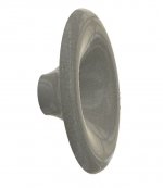
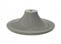
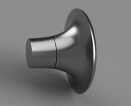
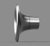
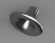
Preparing the first sand-printed one (13"), suitable for a 12" woofer -
(BTW, this was made on the same machine: DEEPTIME | LIFESTYLE AUDIOPHILE SPEAKERS)
(Simulated including a 30° conical exit of a compression driver, e.g. Faital HF108).
(BTW, this was made on the same machine: DEEPTIME | LIFESTYLE AUDIOPHILE SPEAKERS)
(Simulated including a 30° conical exit of a compression driver, e.g. Faital HF108).
Attachments
Last edited:
Cool! Very interesting to follow as now you do your own first realisation!?
Why keeping the size of woofer and WG the same? A woofer at XO radiates form the dustcap/coil former mostly - no?
What XO freq and order planned for this one?
//
Why keeping the size of woofer and WG the same? A woofer at XO radiates form the dustcap/coil former mostly - no?
What XO freq and order planned for this one?
//
Kind of, yeah. I want mainly to test the sand printing with this one.Cool! Very interesting to follow as now you do your own first realisation!?
I expect the crossover around 1 kHz, hopefully somewhat lower - that of course depends also on a particular woofer as not all are the same but it will be around 1 kHz. I think that at that frequency it's still the whole diaphragm that contributes significantly - that's still below break-up and that's why we can use the woofer this high in the first place. You simply want the directivities to match.
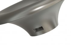
Now I have to devise some mounting.
Last edited:
...
Why keeping the size of woofer and WG the same? A woofer at XO radiates form the dustcap/coil former mostly - no?
...
Woofer starts to narrow it's radiation pattern on a frequency depending on the size. Same goes with the waveguide, it "loses" the pattern control on a frequency depending on it's size. Now when they are both roughly the same size both undergo transition from wide radiation to narrower radiation roughly at the same bandwidth. This is a good spot for crossover, both have similar radiation pattern over a bandwidth and there the combined power and directivity stays as smooth as possible over the crossover region without sudden changes which would happen if you crossed too high of a frequency with smaller waveguide where the waveguide has already lost the control and has much broader radiation pattern than the now beaming bigger woofer. One could cross at lower frequency though, where both the waveguide and woofer have a wide radiation but this is unnecessary stress for the tweeter/compression driver to have lower than necessary crossover.
A big waveguide and a big woofer is to get the crossover point as low as reasonable for the application. a 15" woofer and waveguide would get the crossover under 1kHz, below the most sensitive region of the hearing system.
Last edited:

Wow that looks very nice and I can imagine that sand is a very nice material from a damping standpoint
My experiences with 3d printin horns is that the final heavy cast versions perform better in 100% of the cases, no matter the fill densoty
My experiences with 3d printin horns is that the final heavy cast versions perform better in 100% of the cases, no matter the fill densoty

Looking slick! What will you do to backside of the round-over? What thickness in general are you going for using this sand? Sand & epoxi?
//
//
Now I have to devise some mounting.
I was very happy with using a mounting plate between the driver and the waveguide. The only complication is that the plate needs to have the correct flare in it, but that's not too hard to to.
My experiences with 3d printing horns is that the final heavy cast versions perform better in 100% of the cases, no matter the fill density
I would agree with this as well. My waveguides were so solid that you could not break them even with a sledge hammer. And very well damped due to the filler. The 3D waveguides that I have seen just look far to flimsy to be effective.
Regarding the woofer cone radiating in an ever smaller area, this is true, but it happens much higher than we generally run a woofer. The transition is very slow and start just below the first rim resonance. But we usually don't use a woofer above the rim resonance because it is seldom very effective at that point. So essentially the woofer acts normally as we would expect, except that its polar pattern is a little wider that we would expect from a flat piston of the woofers radius.
- Home
- Loudspeakers
- Multi-Way
- Acoustic Horn Design – The Easy Way (Ath4)