I have checked for DC from the source and have measured around 3mv on each channel. I have many ClassD amps and they all perform as they should with my set up, it is just this one that is a problem.
3mV on each channel is not a problem.
Wonder if there is an important ground-current flowing from your source through the amplifier ground. Could your XH-M590 board power supply have connection to protective earth? If so, try to eliminate the protective earth connection.
Try eventually to connect 1K between the source ground and XH-M590 ground, and 100K between source outputs and XH-590 inputs.
As you describe it, the problem should be in the interface.
Happy new year everyone!
@FauxFrench First of all, thank you for helping so many users with those boards/chips. You've helped a lot of people (me included) improve their amplifiers and I wish you the best this following year.
I followed your instructions on those resistors once my new board arrived. I got one of those Aiyima 2x100W with the Wima caps. Can't be sure if they're fake or not.
AIYIMA Professional Mini Amplificador Audio Amplifiers Board TPA3116 2.0 Dual Chip Digital Power Amplifier 100W For Home Theater|Amplifier| - AliExpress
This board does come with the same issue as others do, a lot of noise when turning the potentiometer. I've been thinking about trying to get a 10 or 5k Log potentiometer that will fit in the board.
Well...other than that, the usual removal of those 75K gain resistors do help a lot. The potentiometer still causes hiss, but you have to get close to the speakers to hear it.
I later then changed the 47k for the correct 5.6k ones, just to keep things clean.
I did manage to change the Bootstrap main caps for a Multilayer one, that didn't give me any noticeable changes.
I then added the last mod I could, that was the snubber mod. This one does change the sound profile quite a lot. This chip does seem to like producing highs that kind of hurts your ears after a while. The snubber mod does fix that and the amp sounds very pleasant, I can now keep it on for hours without issues.
Since I decreased the gain, I didn't want to lose all that power - I don't really have a pre amplifier around and the source I am using is either the BT board I added or a P2 Line from my computer, neither have enough gain.
I then found a very simple pre-amp based on the NE5532 chip in which I could make and managed to add it to my amplifier as a "line" input pre-amplifier. Kinda wish I had a scope to measure things properly, but I only have a half-ok multimeter.
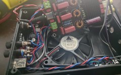
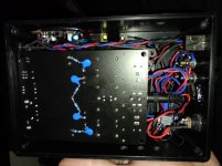
Oddly enough, I found a "DC- Simmetrical converter and isolator", that takes the 24V I use and converts it into 12V+, 0 GND and 12V-. I am unsure how common those things are, but I do have another isolator, for 5V on my Bluetooth board. This did cut down the noise/hiss a lot. So, even adding that pre-amp didn't bring much noise into the system (apart from full volume on the pot).
The 5V isolator is usually found in AliExpress by the name B0505S. The 24-12+/- seems to go by A2412S in case anyone is interested.
They're usually cheap and the "B" version does seem to have a wide range of voltages (B2405 for example).
It's a bit messy in the wiring right now, but here are 2 pictures from before I added the pre-amp.
@FauxFrench First of all, thank you for helping so many users with those boards/chips. You've helped a lot of people (me included) improve their amplifiers and I wish you the best this following year.
I followed your instructions on those resistors once my new board arrived. I got one of those Aiyima 2x100W with the Wima caps. Can't be sure if they're fake or not.
AIYIMA Professional Mini Amplificador Audio Amplifiers Board TPA3116 2.0 Dual Chip Digital Power Amplifier 100W For Home Theater|Amplifier| - AliExpress
This board does come with the same issue as others do, a lot of noise when turning the potentiometer. I've been thinking about trying to get a 10 or 5k Log potentiometer that will fit in the board.
Well...other than that, the usual removal of those 75K gain resistors do help a lot. The potentiometer still causes hiss, but you have to get close to the speakers to hear it.
I later then changed the 47k for the correct 5.6k ones, just to keep things clean.
I did manage to change the Bootstrap main caps for a Multilayer one, that didn't give me any noticeable changes.
I then added the last mod I could, that was the snubber mod. This one does change the sound profile quite a lot. This chip does seem to like producing highs that kind of hurts your ears after a while. The snubber mod does fix that and the amp sounds very pleasant, I can now keep it on for hours without issues.
Since I decreased the gain, I didn't want to lose all that power - I don't really have a pre amplifier around and the source I am using is either the BT board I added or a P2 Line from my computer, neither have enough gain.
I then found a very simple pre-amp based on the NE5532 chip in which I could make and managed to add it to my amplifier as a "line" input pre-amplifier. Kinda wish I had a scope to measure things properly, but I only have a half-ok multimeter.
Oddly enough, I found a "DC- Simmetrical converter and isolator", that takes the 24V I use and converts it into 12V+, 0 GND and 12V-. I am unsure how common those things are, but I do have another isolator, for 5V on my Bluetooth board. This did cut down the noise/hiss a lot. So, even adding that pre-amp didn't bring much noise into the system (apart from full volume on the pot).
The 5V isolator is usually found in AliExpress by the name B0505S. The 24-12+/- seems to go by A2412S in case anyone is interested.
They're usually cheap and the "B" version does seem to have a wide range of voltages (B2405 for example).
It's a bit messy in the wiring right now, but here are 2 pictures from before I added the pre-amp.
Attachments
I then added the last mod I could, that was the snubber mod. This one does change the sound profile quite a lot. This chip does seem to like producing highs that kind of hurts your ears after a while. The snubber mod does fix that and the amp sounds very pleasant, I can now keep it on for hours without issues.
Good to hear more feedback on this mod. I always thought it made a big difference but never quite sure.
has anyone tried the snubber mod on the currently recommended board by FauxFrench - the XH-M950?
Good to hear more feedback on this mod. I always thought it made a big difference but never quite sure.
In my case the biggest difference came from the high frequencies.
The bookshelf speakers I "built" has some tweeters on, and whenever I would listen to music with agressive highs, I would feel my ears ringing a bit, I also had the same issue with my old board when I used 10uH inductors, the old 33uH would cut the high frequencies too short.
I've been thinking about changing the Input Decoupling caps of my board, they're currently 1,5 uF by Wima.
I found some Nichicon Muse BP 10uF caps on Ali, although I am a bit skeptical to give it a try, the store in question has really good rating and they only seem to sell this kind of stuff:
20PCS NEW NICHICON MUSE BP 10UF 50V 8X12MM 50V10UF nichicon MUSE BP 10UF/50V BP ES non polar 50V 10UF|Operational Amplifier Chips| - AliExpress
Thought this could maybe improve a bit my bass response, any opinions on trying such thing? I have no 10uF BP caps to test it out right now...
Edit: The reasoning behind trying to find stuff on Ali is because Mouser/Newark shipping is too expensive for my country (35~40 USD + taxes in which could range to 60% of the products price)
Last edited:
3mV on each channel is not a problem.
Wonder if there is an important ground-current flowing from your source through the amplifier ground. Could your XH-M590 board power supply have connection to protective earth? If so, try to eliminate the protective earth connection.
Try eventually to connect 1K between the source ground and XH-M590 ground, and 100K between source outputs and XH-590 inputs.
As you describe it, the problem should be in the interface.
The power supply is on a piece of wood😀 but in the same way as when I use a plastic case I attache protective earth to the transformer mounting bolt. I will remove it and see what happens.
So far as the 1k and 100k are concerned I do not have a schematic for this board and wonder if you would know where I should make the connections.
Try to disconnect protective earth first. You may have a bit of hum but if your distortion is gone, we look at the hum issue afterwards.
For the 1K and 100K, you need not know the schematic of the power amplifier, nor of the source. The resistors are connected after the output connectors of the source and before the input connectors of the amplifier. Thus, in the cable connection between the two.
I use "open-board" systems because I like experimenting with the circuits continuously. Believe it or not, I have no important hum or distortion problems. Many problems relate to the use of more power supplies in the same signal string.
....................................................
I've been thinking about changing the Input Decoupling caps of my board, they're currently 1,5 uF by Wima.
I found some Nichicon Muse BP 10uF caps on Ali, although I am a bit skeptical to give it a try, the store in question has really good rating and they only seem to sell this kind of stuff:
20PCS NEW NICHICON MUSE BP 10UF 50V 8X12MM 50V10UF nichicon MUSE BP 10UF/50V BP ES non polar 50V 10UF|Operational Amplifier Chips| - AliExpress
Thought this could maybe improve a bit my bass response, any opinions on trying such thing? I have no 10uF BP caps to test it out right now...
Edit: The reasoning behind trying to find stuff on Ali is because Mouser/Newark shipping is too expensive for my country (35~40 USD + taxes in which could range to 60% of the products price)
I normally choose capacitors for a -3dB frequency around 5Hz. I have noticed some Asian designs that uncritically use 100uF-220uF together with a pretty high impedance. Very few speakers, if any, can produce sound below 10Hz. But, a very low cut-off frequency can make your bass cone move in and out quite a lot (without making sound) while it should operate from an equilibrium in the middle of its stroke-range. Thus, unnecessarily low cut-off frequencies are only a disadvantage.
I believe these green MUSE capacitors to be what I use for my best constructions and they are fine, IF you really need 10uF. 1.5uF is enough for most and Wima foil is about the best.
I also buy many components from AliExpress for exactly the same reason.
Last edited:
I normally choose capacitors for a -3dB frequency around 5Hz. I have noticed some Asian designs that uncritically use 100uF-220uF together with a pretty high impedance. Very few speakers, if any, can produce sound below 10Hz. But, a very low cut-off frequency can make your bass cone move in and out quite a lot (without making sound) while it should operate from an equilibrium in the middle of its stroke-range. Thus, unnecessarily low cut-off frequencies are only a disadvantage.
I see... well, I was reading up the datasheet and just found the part where it mentions about the Input capacitors and gain... Considering I am using 20db gain, my current caps are "perfect" then. I guess I don't need to worry about that, but maybe improving my speakers will be the next thing to do. Yeah, it's cheap stuff on a cheaply made box, can't ask much of it.
I believe these green MUSE capacitors to be what I use for my best constructions and they are fine, IF you really need 10uF. 1.5uF is enough for most and Wima foil is about the best.
I also buy many components from AliExpress for exactly the same reason.
That's nice to know! I will hold off on that purchase. I also thought about changing the cheap output caps from my SMPS, it's a cheap-o, so the "Rubycong" caps could probably be changed. Just not sure if it's any worth, that or trying to change the DC ELNA caps on the board.
I will definitely keep that in mind when getting components... The stores here in my country only sells stuff by their standard values. No branding attached (apart from some hare EPCOS/TDK ones appearing here and there, can't even be sure if they're fake).
It was a pain to find the 10uH inductors to use on my older board (I could not find a single seller of any type of inductor here, even if non-branded or outright fake, nothing for the needed ratings..), had to order from Ali, but I got the "not so good" ones. Should have gone for some slightly better I found later.
Good to hear more feedback on this mod. I always thought it made a big difference but never quite sure.
Ohh, my apologies! I just read up on the board where you put out that mod! Good job dude!
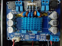
I was about to question if I should have used different values since my board is a dual PBTL. It did help with the "metallic" high notes, but it may have made the highs a bit too muffled... It's better to hear it nonetheless.
Pic attached from my old board, I ended up following someone (can't remember who mentioned..) about just by-passing the entire pre-amp stage, ended up doing that and also added the snubber mod. (Sorry, this board has been really abused...it's been a plaything for me to learn and is currently on a small Home theather central box running at 12V, no need to worry about the underrated 10uH I or the small heatsink)
Attachments
Try to disconnect protective earth first. You may have a bit of hum but if your distortion is gone, we look at the hum issue afterwards.
For the 1K and 100K, you need not know the schematic of the power amplifier, nor of the source. The resistors are connected after the output connectors of the source and before the input connectors of the amplifier. Thus, in the cable connection between the two.
I use "open-board" systems because I like experimenting with the circuits continuously. Believe it or not, I have no important hum or distortion problems. Many problems relate to the use of more power supplies in the same signal string.
I disconnected the PE - No change. I added the 1k and 100k resistors to the OUTS and INS and got barely any volume.
I managed to replace the 75k gain resistors to put the board back to original as I had not used it in this way with my main set-up. It still has some distortion, but not quite as intrusive, but something is clearly not right.
I think I will just have to write this one off as a mis-match. Shame as all my other boards are fine.
1K/100K should give clearly less volume but not almost nothing. Could it be that your volume potentiometer has a low resistance value and your source is suited for higher input impedances? Too hard loading can result in distortion. A smartphone has a headphone output so it can pull almost anything. What do you use as regular system source?
I use a number of Dacs (Cambridge Dacmagic, Muse 4x1541 and others into an LDR Pre, Musical Fidelity X-10D valve buffer and then out to the amp.
Hi to all, I'd need an help.
I wanted to buy an amplifier for these speakers, since I already have m100 dac I wanted to take an smsl sa100 but I read everywhere that tpa3116 has noise issues. Is it true? I'm a newby and I don't want to modify anything on the board. So I'm stuck to the same question: 3116 or 3250?
I wanted to buy an amplifier for these speakers, since I already have m100 dac I wanted to take an smsl sa100 but I read everywhere that tpa3116 has noise issues. Is it true? I'm a newby and I don't want to modify anything on the board. So I'm stuck to the same question: 3116 or 3250?
I use a number of Dacs (Cambridge Dacmagic, Muse 4x1541 and others into an LDR Pre, Musical Fidelity X-10D valve buffer and then out to the amp.
Sorry for the delay in responding.
It is a vacuum tube construction of high quality with an output impedance below 200 Ohm. Unfortunately I know very little about vacuum tube constructions but I believe the impedance level to be higher than for recent solid-state constructions.
Have you tried to connect the DAC-Magic directly to the XH-M590? The DAC-Magic has at least JRC5532 (or better) OP-AMPs in the output stage. The DAC-Magic should be able to pull the XH-M590 without problems.
Sorry for the delay in responding.
No problem, we all have stuff that gets in the way of the more important task of tinkering with audio😀
I will try a different route for the signal and see what that does. In the meantime and during lockdown here I dug out some LM3875 Monoblocks I made years ago which have been gathering dust and did a few mods to those. So long since I heard them I need to tune in to them again.
Hi guys, I'm new to audio components so please forgive the beginner question.
I'm wanting a 2.1 amp with APTX Bluetooth, and particularly interested in TPA3116D2 because of the low price
I've been looking on AliExpress at this product:
AIYIMA APTX Bluetooth 5.0 Subwoofer Amplifier Audio Board 50Wx2+100W TPA3116 2.1 Power Sound Speaker Amplifies Home Mini AMP|Amplifier| - AliExpress
I notice some 2.1 amps have a subwoofer frequency dial and some don't. From what I read on forums it isn't a proper crossover or cutoff?
Is the subwoofer frequency dial just a gimmick? Or actually useful?
Can a 4 channel amp be used as 2.1?
Just remove the two 75K resistors, no bridging.
You can remove the potentiometer but it can prove useful later to adjust the amplifier sensitivity. If you remove it, you should replace it with two, not more than 10K resistors between the outer terminals for each channel AND connect (bridge) the middle terminal to the right terminal (seen from the potentiometer axis and the component side) for each of the two channels. The 10K resistors ensure a reasonably low input impedance (which is also important for keeping the TPA3116 amplifier noise down) and the two bridges leave connections as if the potentiometer was turned clockwise for full volume.
I have a similar board and have converted it to differential input by connecting the signal inputs directly to the coupling capacitors (bypassing the pots).
I'm thinking that I need to match the input impedance as well. I would need to tie each differential signal to ground independently with 10K resistors? (4 resistors then? LP, LN, RP, RN) Or only the + side?
Perfect. I’ve seen some suggest using a smaller value for some boards. Without actually going to the trouble to measure the input impedance how do i go about picking the right value? (Or is it not that sensitive)
- Home
- Amplifiers
- Class D
- TPA3116D2 Amp