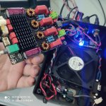
I just switched from this tpa3116 and this Bluetooth module to this Wondom tpa3116 based amp with built in Bluetooth.
My battery life has taken a severe beating. It could be coincidence and it's a damaged battery, I've ordered a battery tester so I can test that. But is there anything else it might be? I would have expected the sure audio unit to be more, not less, efficient...
Sound quality wise the amps are in completely different leagues to eachother, as can be expected by the price difference.
Last edited:
Seems like a very serious design that Wondom. But, mono amp. with BlueTooth? What do you do if you want stereo? Use the same Bluetooth module on one of the boards?
You have good access for mods but very few are needed. It is a good initial implementation.
Yep, I think that board is a good initial one. And wow, those Wondom boards do look nice, but they're really populated eh? There's not a single bit without stuff xD
I went with the Aiyima design (with Wima caps) and well... the lack of a screw on heatsink is kinda bothersome when changing some stuff under them.
After reading the datasheet I noticed my filter caps are a bit under the nominal values recommended for the PBTL boards (680nF instead of 1uF), that doesn't seem to be causing issues though.
I ended up removing the Snubber mod on mine, was missing the high end details.
My first project is almost done here, are pictures welcome here? 😱
Seems like a very serious design that Wondom. But, mono amp. with BlueTooth? What do you do if you want stereo? Use the same Bluetooth module on one of the boards?
It is used in a mono speaker build, so this was pretty much the only option for mono with built in Bluetooth.
Pictures of DIY-constructions are welcome. Please do not exaggerate the size of each picture. 1280x1024 should do
Pictures of DIY-constructions are welcome. Please do not exaggerate the size of each picture. 1280x1024 should do
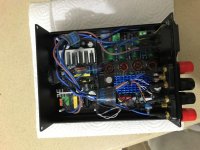
There you have some, and an extra.
I was able to get my hands on a original OPA2132 and 2 TPA3116's, they're all in use in this one.
I think I will remove the pot from the board though and move it before the signal reaches the Pre-amp to avoid noise. The only noise I hear is when the pot is between mid point. Near low volume or maximum there's no noise at all (even placing my ear over the tweeter). Kinda impressive as I think my wiring is pretty cheap and simple.
To me it sounds amazing right now. I wish I had an scope to measure things right.
What would you look for in testing it with a Multimeter? 😛
Attachments

Nice compact build! I believe it is better to buffer the signal first using an opamp and then have the volume pot between that and the amplifier input.
How do you power the opamp? Using a separate dual power supply?
How do you power the opamp? Using a separate dual power supply?
Nice compact build! I believe it is better to buffer the signal first using an opamp and then have the volume pot between that and the amplifier input.
How do you power the opamp? Using a separate dual power supply?
I think the way things are it's pretty much like that regarding the pot? The signal comes in, goes through the pot before reaching the 1,5uF filter caps on that board, it's what it seems.
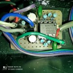
I am using one of those Converter/Isolators. You can see it on the second picture, it has a tiny heatsink on it's side (bottom corner on second pic).
It takes 24V and converts to simmetrical 12V (+-12). I think it works similarly to some voltage regulator setups, but provides only low current. More than enough for the OPAmp. I also have a 5V one for the bluetooth board.
Last edited:
Nice construction.
Be careful if you try to remove such a stereo-potentiometer with ON/OFF switch. My personal experience is that the potentiometer may survive but some of the PCB pads and tracks near the potentiometer may not. My solution is often to let the potentiometer stay and turn it fully up. That way it bothers nobody.
I use a multimeter (Ohm-meter setting) to check that the connections are correct before putting power on. It is easy to make a mistake and in particular wrong power connections can be fatal. Such a check lasts 10-15 minutes and can save you hours later on.
Nice construction.
Be careful if you try to remove such a stereo-potentiometer with ON/OFF switch. My personal experience is that the potentiometer may survive but some of the PCB pads and tracks near the potentiometer may not. My solution is often to let the potentiometer stay and turn it fully up. That way it bothers nobody.
I use a multimeter (Ohm-meter setting) to check that the connections are correct before putting power on. It is easy to make a mistake and in particular wrong power connections can be fatal. Such a check lasts 10-15 minutes and can save you hours later on.
Never done the Ohm meter thing. I just have a thing about checking my wiring about 5 times over before plugging in.
When I do plug in, I use one of those voltage converters to limit both the voltage and current in case there's a massive fail, limiting the voltage to 9~12V before plugging into my 24V SMPS. It's just as much work I guess, but I haven't done a big fail yet. 😀
Thank you for the recommendation! I will keep that in mind if I try to remove it. I don't have a resoldering station with hot air, only a temp controlled iron with a knife tip (was good enough to safely remove and replace the TPA3116 chips).
I had done wrecked one of my test boards already before getting the temp controlled iron 😱
I will soon receive some of the BP caps I mentioned some time ago, got them for fairly cheap. I might change all those filter caps into them just because haha
I think I will remove the pot from the board though and move it before the signal reaches the Pre-amp to avoid noise. The only noise I hear is when the pot is between mid point. Near low volume or maximum there's no noise at all (even placing my ear over the tweeter).
In my very limited experience, a couple of the potentiometer-equipped XH 3116D2 boards I've used (M577) do not supply ground to the cases of the potentiometers. I was able to solve all of my potentiometer noise issues by running a jumper from the audio ground at the input to a groundplane connecting all of the pots. Might be worth checking on your board.
In my very limited experience, a couple of the potentiometer-equipped XH 3116D2 boards I've used (M577) do not supply ground to the cases of the potentiometers. I was able to solve all of my potentiometer noise issues by running a jumper from the audio ground at the input to a groundplane connecting all of the pots. Might be worth checking on your board.
Oh that was a good hint! I gave a look at my board and noticed there's a small "ground" point near my pot. I wrapped a wire around the pot's metal part and soldered it to that ground point.
It did help quite a bit, not entirely, but there's definitely less hiss and the volume seems quieter during change.
Once I receive my filter caps, I will change the input filter and add more gain (either 26 or 32 DB). The noise was really bad even on 26 DB gain for this before.
Thank you!
I'm glad to hear it helped. I suspect that the people designing the boards assume that integrators will panel mount via the pots to ground them... either that, or they just don't give a toss 😉
I think the way things are it's pretty much like that regarding the pot? The signal comes in, goes through the pot before reaching the 1,5uF filter caps on that board, it's what it seems.
I am using one of those Converter/Isolators. You can see it on the second picture, it has a tiny heatsink on it's side (bottom corner on second pic).
It takes 24V and converts to simmetrical 12V (+-12). I think it works similarly to some voltage regulator setups, but provides only low current. More than enough for the OPAmp. I also have a 5V one for the bluetooth board.
I didn't know these existed. This makes it so much easier to run an opamp from the same dc power supply.
The datasheet provides no schematic for typical application, but states that a capacitor on the input and output is needed, as well as a resistor parallel on the output to provide a minimum load.
It also states that for 'extremely low ripple' an LC network should be used on the input and output.
Did you use an LC filter? And if so, how are the values calculated?
Hello MaonaHello.I am thinking of buying my first class D amp generally based on TPA3116D2.There are many posts and difficult to read all of them.Is this a good and reliable PCB design to buy ? Any downsides of this board? model is XH-M590
The board is very good indeed just as Faux French advises. please use the link below to see my review and a comparison with a 3886.
Cheers
I didn't know these existed. This makes it so much easier to run an opamp from the same dc power supply.
The datasheet provides no schematic for typical application, but states that a capacitor on the input and output is needed, as well as a resistor parallel on the output to provide a minimum load.
It also states that for 'extremely low ripple' an LC network should be used on the input and output.
Did you use an LC filter? And if so, how are the values calculated?
I am a beginner in electronics, so I still have no idea on how to calculate those yet, sorry.
Those modules are great though. I found them looking for a way to isolate my bluetooth board (B series) and then found the simmetrical designs (A Series). Some big brands such as Wurth has some of the B type isolators/converters and they're completely external component free.
My setup is only using near the recommended capacitors. It asks for a 2.2uF in 12V and 1uF in 24, I just used the 2.2uF in both, had no issues so far, mine is also sending power directly into my OPA at turn on, so I think I don't need a load resistor, but I might be really wrong here, not sure.
I'm glad to hear it helped. I suspect that the people designing the boards assume that integrators will panel mount via the pots to ground them... either that, or they just don't give a toss 😉
Yeah, I believe my problem is that I am using a plastic housing. It was the cheaper method I found, to just buy a normal box and drill the holes I needed into it 😛
Anyways, if delivery doesn't fail me, my caps should arrive today or tomorrow for testing.
- Home
- Amplifiers
- Class D
- TPA3116D2 Amp