Hi TPA3116 gurus:
I’ve changed direction in my project slightly and decided to go down the avenue of the Dayton audio/wondom/sure dsp-enabled TPA3116 boards.
I finally had a set of mods that i liked on my last set of boards (random amazon vendor) and i’d like to move them over (wima input caps, correct bootstrap caps, etc).
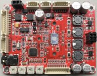
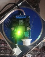
The problem is, I don’t recognize the circuit well enough on these boards to find the input and output caps. I have no problem finding the bootstrap caps, but the output has a huge wide resistor where i would have expected the output cap. They are also doing some strange stuff with diodes in the output filtering as well. Alongside smaller inductors than i was expecting.
Do you guys have any experience with these boards?
I’ve attached the images of the boards. I’m happy to beep out any traces you need to figure it out.
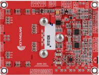
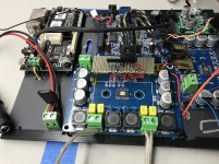
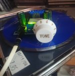
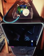
I also added the last known working configuration of the board i am trying to use as a reference (foreground in the center)
I’ve changed direction in my project slightly and decided to go down the avenue of the Dayton audio/wondom/sure dsp-enabled TPA3116 boards.
I finally had a set of mods that i liked on my last set of boards (random amazon vendor) and i’d like to move them over (wima input caps, correct bootstrap caps, etc).
The problem is, I don’t recognize the circuit well enough on these boards to find the input and output caps. I have no problem finding the bootstrap caps, but the output has a huge wide resistor where i would have expected the output cap. They are also doing some strange stuff with diodes in the output filtering as well. Alongside smaller inductors than i was expecting.
Do you guys have any experience with these boards?
I’ve attached the images of the boards. I’m happy to beep out any traces you need to figure it out.
I also added the last known working configuration of the board i am trying to use as a reference (foreground in the center)
Attachments
Hi,
I had this
US $13.78 37%OFF | 2018 NEW TPA3116 official version 50W +50 W.
2018 NEW TPA3116 official version 50W +50 W.|50w 50w| - AliExpress
Really good quality. I recommend
An today of I had to order new amp board I would test
This:
US $14.32 18%OFF | GHXAMP TPA3128 Digital Power Amplifier Board 2*30W HIFI Stereo Audio Amplifier Class D 26dB DC5-24V For Portable Speaker Diy 1pc
GHXAMP TPA3128 Digital Power Amplifier Board 2*30W HIFI Stereo Audio Amplifier Class D 26dB DC5 24V For Portable Speaker Diy 1pc|Amplifier| - AliExpress
I already own the big brother (tpa3221) and he is very good.
Yours
Hi TPA3116 gurus:
I’ve changed direction in my project slightly and decided to go down the avenue of the Dayton audio/wondom/sure dsp-enabled TPA3116 boards.
I finally had a set of mods that i liked on my last set of boards (random amazon vendor) and i’d like to move them over (wima input caps, correct bootstrap caps, etc).
The problem is, I don’t recognize the circuit well enough on these boards to find the input and output caps. I have no problem finding the bootstrap caps, but the output has a huge wide resistor where i would have expected the output cap. They are also doing some strange stuff with diodes in the output filtering as well. Alongside smaller inductors than i was expecting.
Do you guys have any experience with these boards?
I’ve attached the images of the boards. I’m happy to beep out any traces you need to figure it out.
I also added the last known working configuration of the board i am trying to use as a reference (foreground in the center)
Those populated boards must be a nightmare to find stuff if you don't have a schematic for it. Maybe Dayton can provide you a schematic? Try contacting them, it could be a lot easier this way, or just ask what capacitors are the input ones, sometimes they might not share the schematic but could give you this info.
On that blue board you have, you could take a look at this link:
TPA3116D2 2 channel Amprefire Modification
This was done by CyberPit, but it describes a lot of modifications that board can receive. Although, if there was a single recommendation I can make, is to change those 33uH inductors, otherwise you'll have no detail in high frequencies. I can recommend these, that should fit that board well:
7447709100
Hi,
I had this
US $13.78 37%OFF | 2018 NEW TPA3116 official version 50W +50 W.
2018 NEW TPA3116 official version 50W +50 W.|50w 50w| - AliExpress
Really good quality. I recommend
An today of I had to order new amp board I would test
This:
US $14.32 18%OFF | GHXAMP TPA3128 Digital Power Amplifier Board 2*30W HIFI Stereo Audio Amplifier Class D 26dB DC5-24V For Portable Speaker Diy 1pc
GHXAMP TPA3128 Digital Power Amplifier Board 2*30W HIFI Stereo Audio Amplifier Class D 26dB DC5 24V For Portable Speaker Diy 1pc|Amplifier| - AliExpress
I already own the big brother (tpa3221) and he is very good.
Yours
I've been looking at that tiny 3128 for a while, seems like a good quality one and all the filters does seem to use correct values specified in the datasheet, except the input ones, which are 1uF, but for a 26Db gain you should use a 3.3uF, guess you could either decrease the gain or change the input caps.
Those populated boards must be a nightmare to find stuff if you don't have a schematic for it. Maybe Dayton can provide you a schematic? Try contacting them, it could be a lot easier this way, or just ask what capacitors are the input ones, sometimes they might not share the schematic but could give you this info.
On that blue board you have, you could take a look at this link:
TPA3116D2 2 channel Amprefire Modification
This was done by CyberPit, but it describes a lot of modifications that board can receive. Although, if there was a single recommendation I can make, is to change those 33uH inductors, otherwise you'll have no detail in high frequencies. I can recommend these, that should fit that board well:
7447709100
Thanks, I think you may have misunderstood. I have already modified the blue board, but I'm trying to move the mods to the red board. It appears to have a strange diode-based output filter on it that I do not recognize.
Thanks, I think you may have misunderstood. I have already modified the blue board, but I'm trying to move the mods to the red board. It appears to have a strange diode-based output filter on it that I do not recognize.
Hey, my apologies, it was more of a recommendation to improve the high frequency on them, I have a similar board. 🙂
On that Dayton board, when tracking back from pins 4,5,10 and 11 (inputs to 3116D2) the capacitors C13 and C8 seems to be the Right Input and C18/21 for the left side.
At least, those are the closest ones to the chip. If they're 1uF, theres a good chance they might be the input filters. Then again, that board is very complex and I might be wrong, could be worth checking those out.
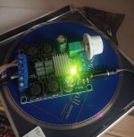
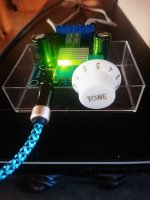
Got this 2 for 1 sale on amazon US for $13.49. Some pics. I just got it and sounds great at half volume. Only one speaker(not really great sounding more of surround speaker, but clear enough) hooked up for listening and used my player with Flac files. Used a 12volt cable I had laying around and spliced it. It can take 24v, so it can go louder! Used a guitar knob I had and looks neat. I'll make a DIY case later.
Attachments
I am trying to diagnose a new issue with my XH-M577 board. I've suddenly lost audio output on the left channel. The right channel is working normally. There are no audio cutouts or ticking/popping.
I used my multimeter and traced through my input signal chain (L&R analog inputs connected via JST cable > aux input header on JQ-D082 bluetooth module > JST cable output to M-577 amplifier input.) I could find no faults in the signal chain - I had continuity where expected and matching resistance on L/R channels where expected. The lack of output on the left channel was the same regardless of input source selected through the BT module: analog, bluetooth, FM tuner, USB/SD media.
I traced through my output path (M-577 speaker out > speaker protection/relay board (modified to work with BTL amp > speakers) with similar results: no problems found. The relays on the protection board are closing properly and I have continuity from amp to speakers when powered on.
I swapped my speaker leads left-to-right to verify that the speakers themselves did not have a fault, and the lack of output followed from left to right. The speakers are all working fine.
Then I started checking DC voltages. Voltage on both L&R channels seem nominal coming out from the BT module to the amp, or at least, the voltages were equal.
However, when I checked DC voltage out from amp, I found that at about middle volume I was seeing ~12V on the right channel, but only ~8.5-9V on the left channel. Output voltage at the amp was tested directly at the solder points for the speaker cable output headers.
This leads me to believe that the problem is localized to the amplifier board itself. Has anyone else encountered a similar issue with reduced output voltage only on one channel on their TPA3116 board? Does this sound more like an internal chip problem, or is it more likely to be related to a fault in an external component like a capacitor or resistor? Where would you suggest I start looking?
The output DC voltage of the TPA3116 chip should be about 1/2 of the supply voltage. Each speaker connection should be the same. With no input signal and the volume pot at 0 every speaker connection should see about 12 Volts DC if your power supply is 24 VDC.
The inputs to the TPA3116 are AC coupled and have DC blocking capacitors on its inputs. If you have only one opamp on your board the out put pins are most likely Pin 1 and Pin 7 of the opamp. Pins 1 and 7 usually are at 1/2 of the DC supply voltage of the opamp power supply pin 8.
There are many Free Sine wave generators you can install on your phone or tablet. You can set the sine generator to 50/60 HZ and set your meter to AC volts and try to follow the AC signal. If you have some resistors you can connect to your amp instead of speakers that would be helpful as its difficult to trace a few millivolts with a meter. AN oscilloscope would be helpfull here. The bluetooth output may only be 250 millivolts AC when the volume of your phone is at 100%
First check (without power or speakers): Check the resistance from each of the two outputs and to power supply "-" and following to power supply "+" (4 measurements). Anything below 100Ohm may indicate a faulty chip.
If OK, I believe the problem may be on one of the two input lines to that faulty channel. Eventually a signal coupling capacitor that leaks (electrolytic).
If OK, I believe the problem may be on one of the two input lines to that faulty channel. Eventually a signal coupling capacitor that leaks (electrolytic).
With no input and volume at zero, I am seeing ~10.5V on the right output, and ~7.5V on the left output. Power supply is 24V, and power measured to board is 23.8V.The output DC voltage of the TPA3116 chip should be about 1/2 of the supply voltage. Each speaker connection should be the same. With no input signal and the volume pot at 0 every speaker connection should see about 12 Volts DC if your power supply is 24 VDC.
This board has two NE5532 opamps at the inputs. I'm really an amateur, so am unsure how the pinout configuration/interconnection may vary on this board vs a design for one opamp, but will check and see what I come up with.The inputs to the TPA3116 are AC coupled and have DC blocking capacitors on its inputs. If you have only one opamp on your board the out put pins are most likely Pin 1 and Pin 7 of the opamp. Pins 1 and 7 usually are at 1/2 of the DC supply voltage of the opamp power supply pin 8.
I only have a very basic multimeter, and no oscilloscope (not that I'd know how to use one if I had!). I don't have any suitable resistors to supply a test load unfortunately. When you mention following the AC signal, this refers to the input side, or am I looking for propagation on the board itself? Thanks for your help & input!There are many Free Sine wave generators you can install on your phone or tablet. You can set the sine generator to 50/60 HZ and set your meter to AC volts and try to follow the AC signal. If you have some resistors you can connect to your amp instead of speakers that would be helpful as its difficult to trace a few millivolts with a meter. AN oscilloscope would be helpfull here. The bluetooth output may only be 250 millivolts AC when the volume of your phone is at 100%
I have no continuity on my meter on either "-" or "+" between outputs and power supply, with power off and speakers disconnected. Not sure if this constitutes "ok" or not. Thank you for your input!First check (without power or speakers): Check the resistance from each of the two outputs and to power supply "-" and following to power supply "+" (4 measurements). Anything below 100Ohm may indicate a faulty chip.
If OK, I believe the problem may be on one of the two input lines to that faulty channel. Eventually a signal coupling capacitor that leaks (electrolytic).
I assume that "no continuity" means "high impedance". If so, the result is OK.
Can you see the signal coupling capacitors at the input of the faulty channel?
Can you see the signal coupling capacitors at the input of the faulty channel?
Regardless of range setting on the meter, it returned "infinity" across each path. So, yes, very high impedance.I assume that "no continuity" means "high impedance". If so, the result is OK.
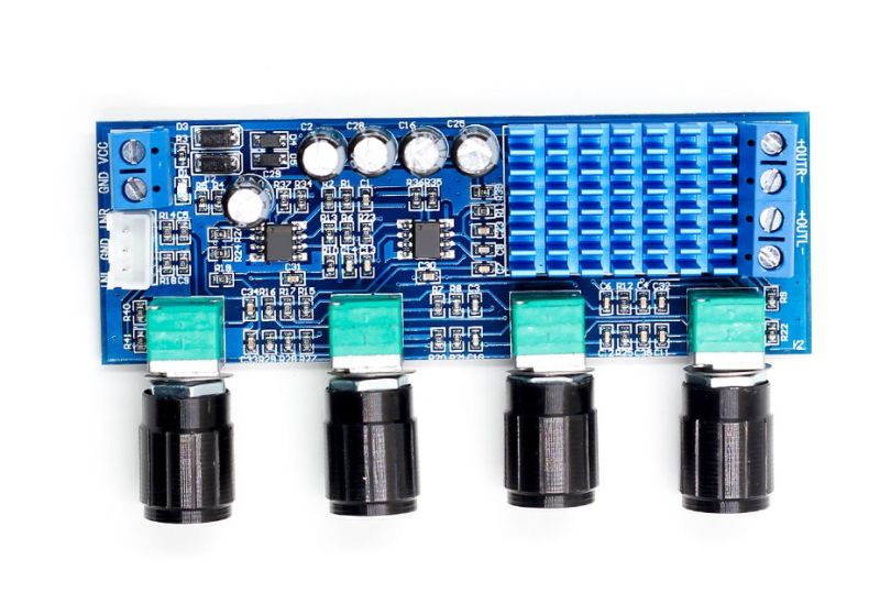
This is my amp model. Are the electrolytics C2/C28/C16/C25 what I want to look at, or might they be surface mount? I'll need to remove the board from its cabinet to visually inspect the caps - just looking for leaky/swollen/bulged caps, right? Thanks again!
I swapped my speaker leads left-to-right to verify that the speakers themselves did not have a fault, and the lack of output followed from left to right. The speakers are all working fine.
For this reads exactly as a defunct speaker😉
For this reads exactly as a defunct speaker😉
I may have worded that poorly! Left speaker produced output when connected to Right amp channel 😉
Please first take account of bucks bunny's very relevant observation and comment: "the lack of output followed from left to right"!
What we are looking for is capacitors corresponding to C11-C14 (1uF) in figure 37 of the datasheet ( https://www.ti.com/lit/ds/slos708g/...428467&ref_url=https%3A%2F%2Fwww.google.it%2F ).
The electrolytic capacitors you mention seems to be power rail decoupling capacitors, not what we are looking for.
The purpose of these four capacitors is to allow only AC signals to reach the IC inputs. On the IC side of the capacitors there are build-in bias circuits that put the input DC levels at a correct value. If a capacitor has a high leakage current (faulty), the input cannot settle at the correct DC level for which reason the output will not settle at the right DC value. Then, the DC-protection circuit will detect a DC failure and not turn the channel ON.
I normally find these capacitors by removing the heatsink and find the input pins on the IC. Then I go backwards from the input pins until I reach the capacitors.
But, a next problem: Your heatsink seems to be glued to the chip so it is difficult to remove. The capacitors may very well be below the heatsink.
A defect (leaking) capacitor needs not show any sign of deformation.
You better get the board out so you have good access.
- Home
- Amplifiers
- Class D
- TPA3116D2 Amp