hello NMOS ,
I have not problem with my pc board on BGW,i will just fix it up and some improvements.
the google translation must not be perfect, there must be some bad translation.
I said that our work was magnificent.
Phil
I have not problem with my pc board on BGW,i will just fix it up and some improvements.
the google translation must not be perfect, there must be some bad translation.
I said that our work was magnificent.
Phil
You cant do much,
it was a great bass amp in the 70s,
about 35V AC Output power,
very stable working circuit design driving large subwoofers, sounding fine also fullrange until today
easy to update for todays standards. Improvement for small and medium power up to +/- 120 V DC to get 65V AC 1000W RMS @ 4Ohm output Power are switched rails Class TD / EEEngine to avoid heat dissipation and todays output devices
For high output Power +/-95 V DC Rail
Todays Standard is Fullbridge Class D to get 100V AC output Power 2500W RMS @ 4 Ohm
Last edited:
Here is the photo which shows some improvement as described
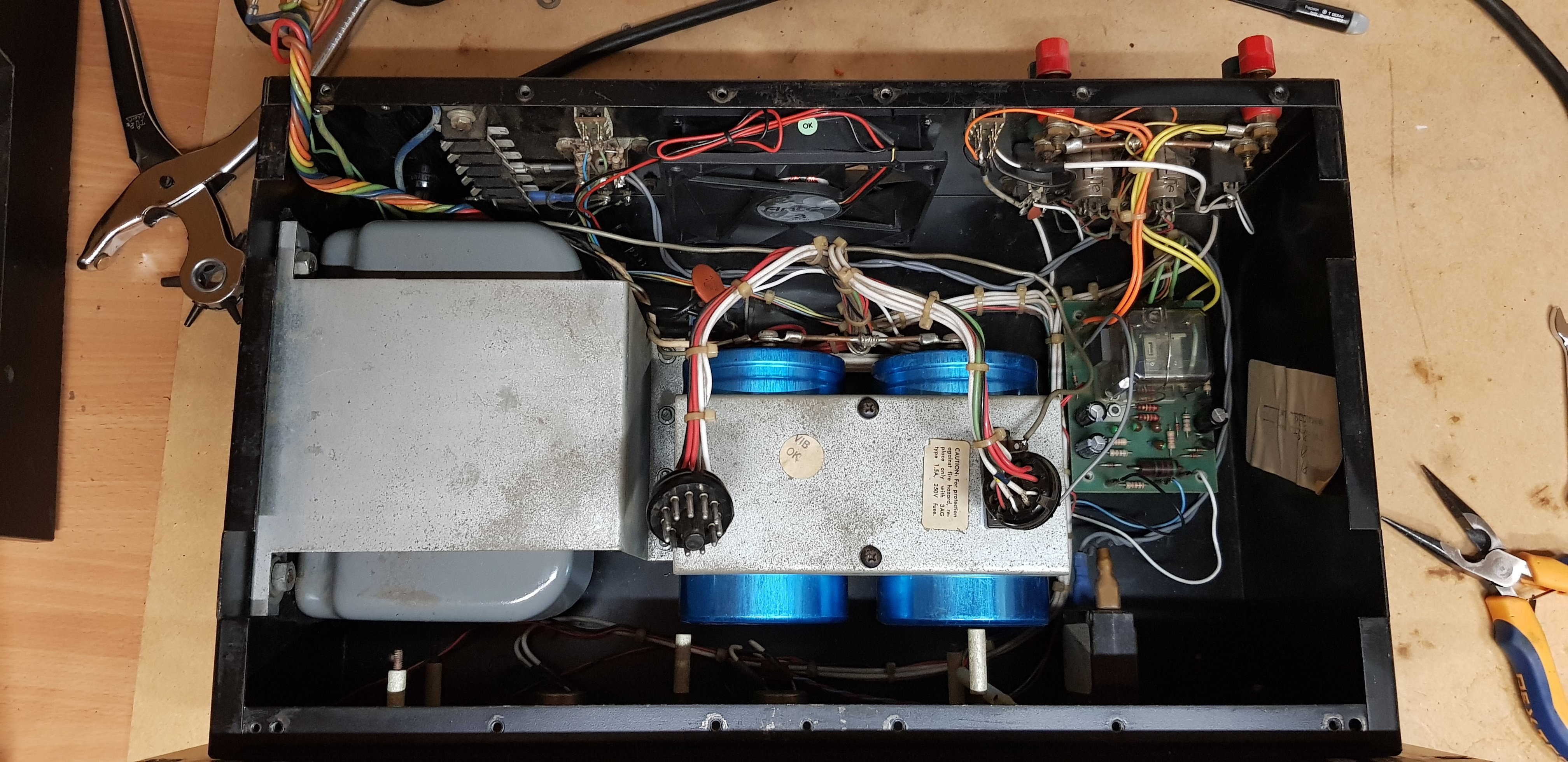
1-complete disassembly and cleaning of the condos - transformer - relay board and the chassis.
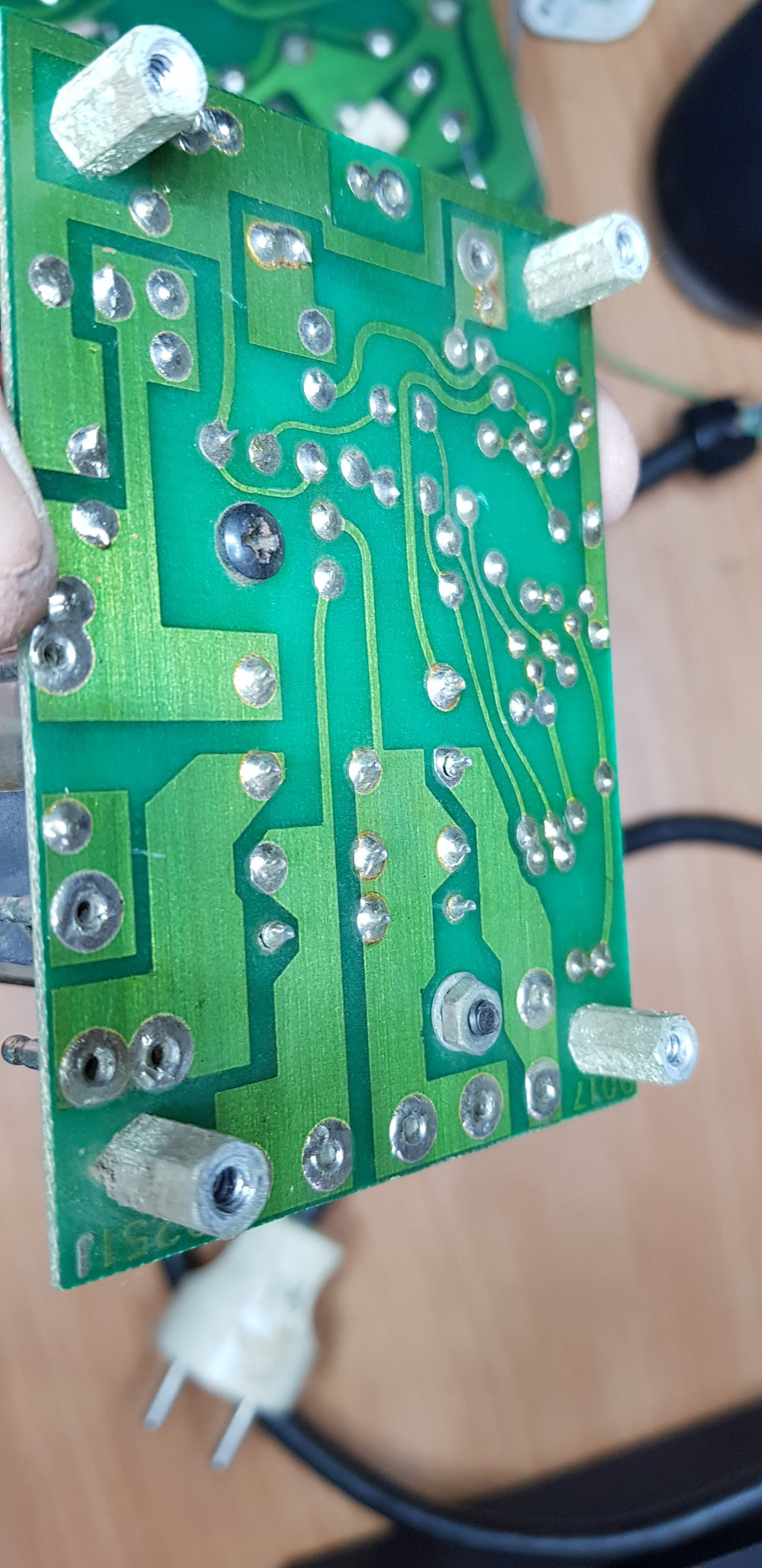
2- Replaced the 3 330uf condos on the protection relay plate and re-soldered all the relay terminals because the welds were broken in 3 places.
3-Replaced the original fan with an adjustable 3-speed Antec PC fan.
(secondary 12vdc power supply to be provided) my initial idea was to take the voltage of the 15vdc available for the view-meters and use it for the fan but after advice from various people, it is preferable to isolate it by another power supply .
4- felt placements under the 2 transformer fixing points for its resonance on the sheet.
5- for the moment not yet received parts for the Amplifier part (transistors and 3 chemical condos)
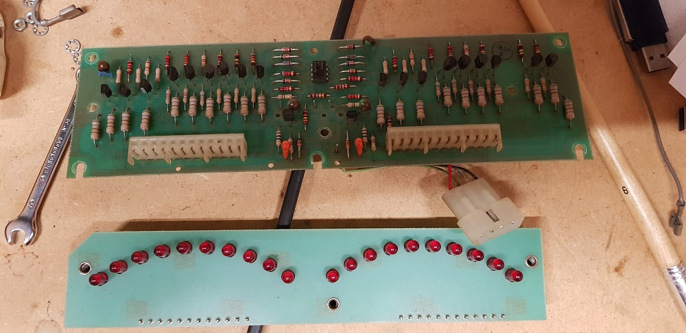
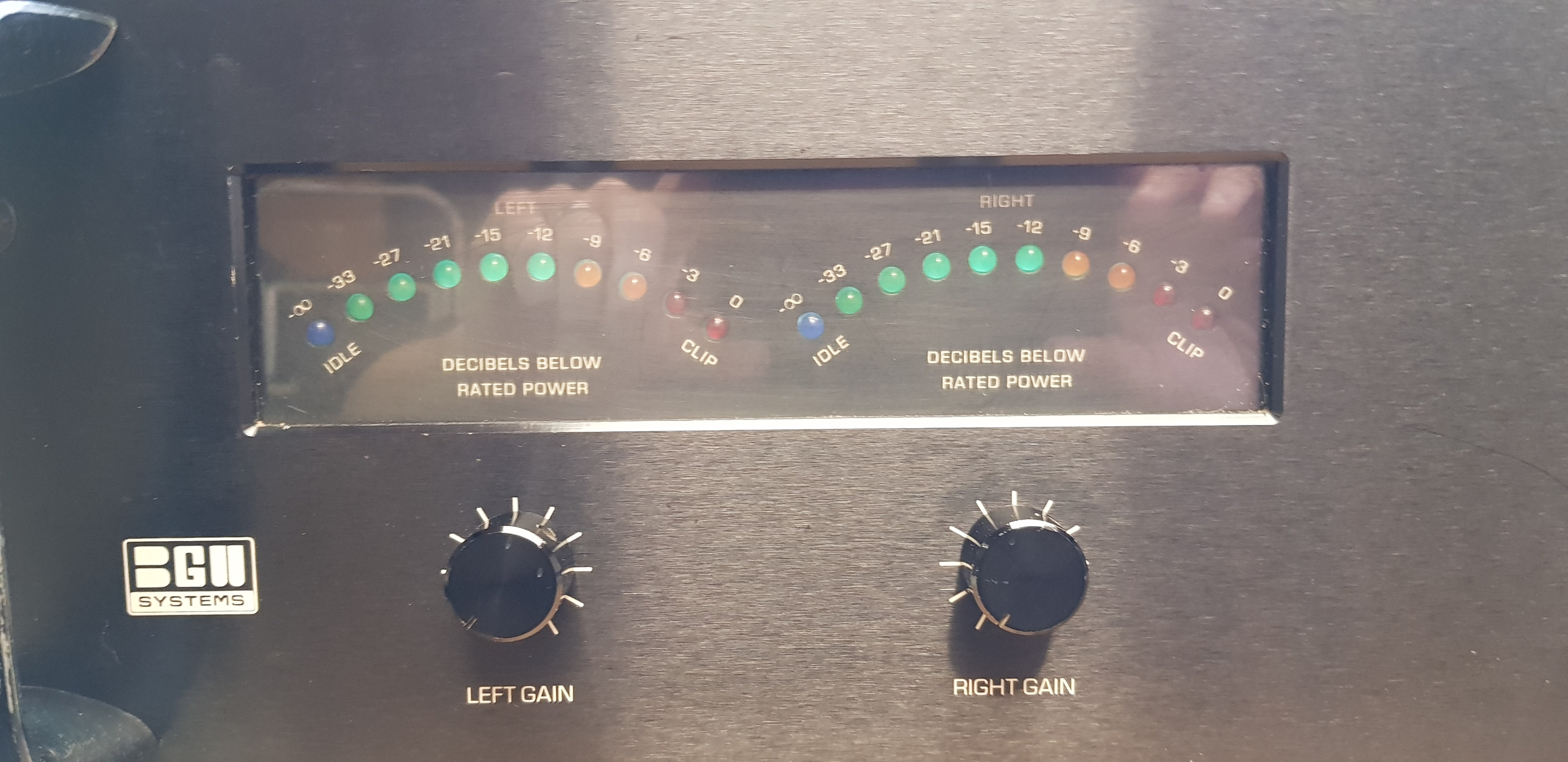
6- change of the Red LEDs by a green and yellow part as on an American model. (waiting for leds)
photo after cleaning, replacements and modifications and reassembly.
Red sight-meter part which will be replaced by 5 green leds and 5 yellow leds as on this photo found.
to follow, I await my components , Phil
1-complete disassembly and cleaning of the condos - transformer - relay board and the chassis.
2- Replaced the 3 330uf condos on the protection relay plate and re-soldered all the relay terminals because the welds were broken in 3 places.

3-Replaced the original fan with an adjustable 3-speed Antec PC fan.
(secondary 12vdc power supply to be provided) my initial idea was to take the voltage of the 15vdc available for the view-meters and use it for the fan but after advice from various people, it is preferable to isolate it by another power supply .
4- felt placements under the 2 transformer fixing points for its resonance on the sheet.
5- for the moment not yet received parts for the Amplifier part (transistors and 3 chemical condos)
6- change of the Red LEDs by a green and yellow part as on an American model. (waiting for leds)
photo after cleaning, replacements and modifications and reassembly.

Red sight-meter part which will be replaced by 5 green leds and 5 yellow leds as on this photo found.


to follow, I await my components , Phil
hello
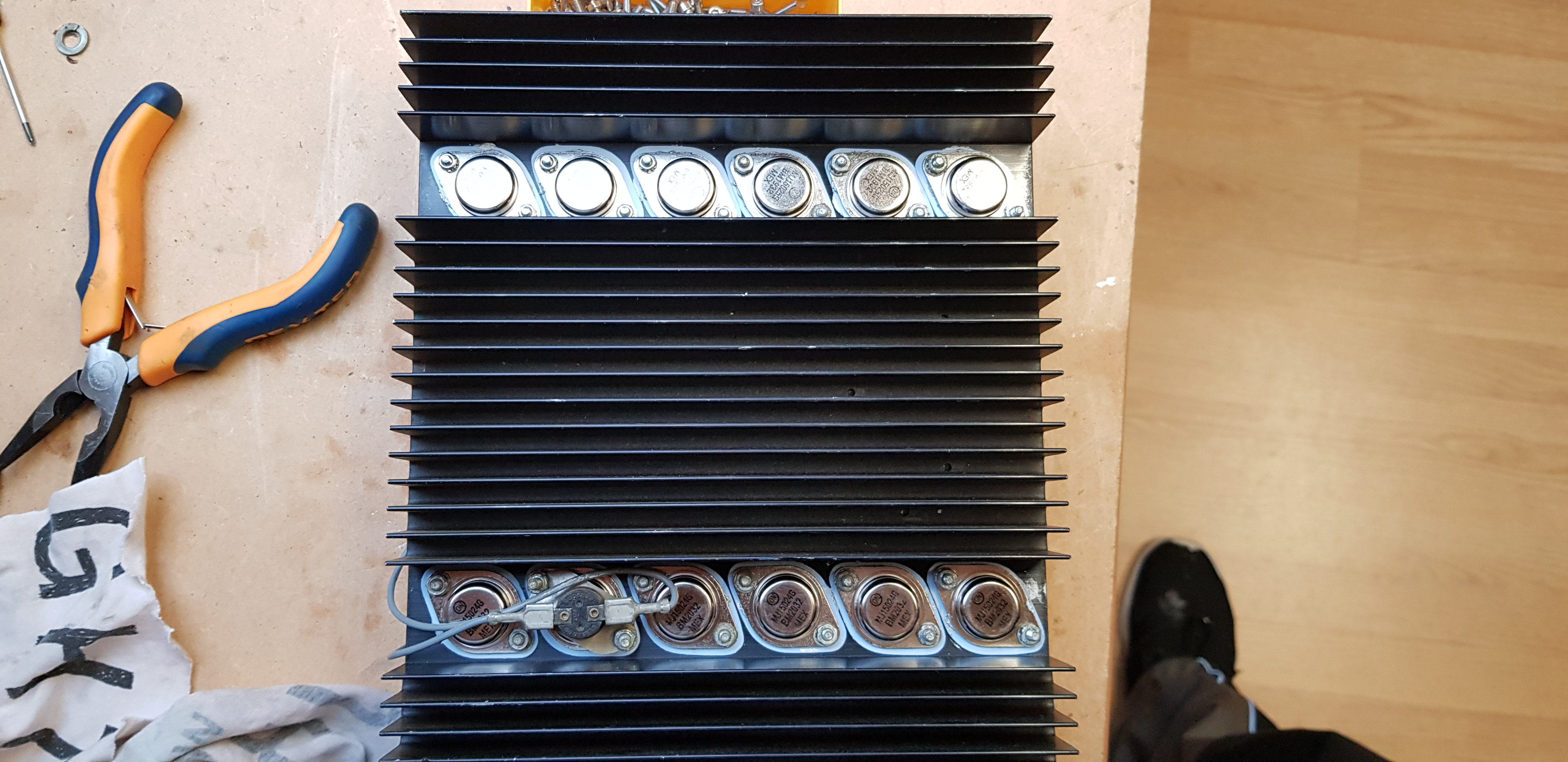
I went a little further, I mounted the output transistors with silicone insulators as well as for the 5 driver transistors.
I replaced my VU meter LEDs and placed 4 feet under the frame.
I am still waiting for the rest of my components ...
Phil
I went a little further, I mounted the output transistors with silicone insulators as well as for the 5 driver transistors.
I replaced my VU meter LEDs and placed 4 feet under the frame.


I am still waiting for the rest of my components ...
Phil
Hello,
I reassembled the output transistor part, first soft start on the 90volt autotransformer.
I check a few voltages in different places to verify that everything is correct but I realize that at the output of the LM 318 I have on the Right channel which is still operational and of -240mv origin.
except on the Left channel which has just been repaired I have + 450mv. I have a doubt about the LM318 which is broken, however when I put an audio source I have the sound coming out of the two channels at the same power without distortion
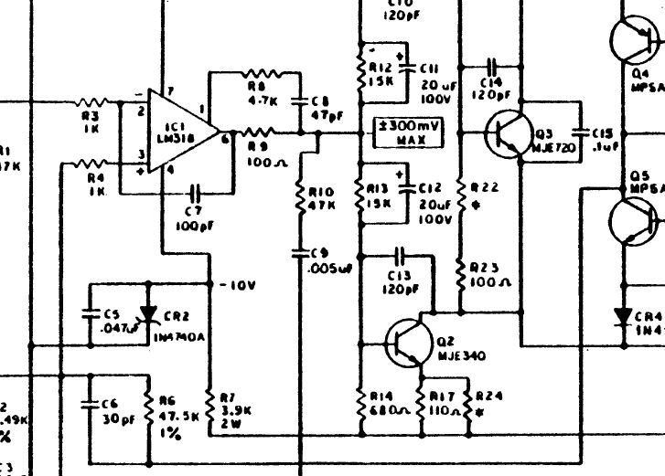
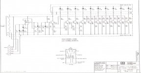
on the BGW diagram it is written +/- 300mv.
there I do not really understand if we must be in the positive or in the negative because +/- does not really mean the good sense of the current.
Phil
I reassembled the output transistor part, first soft start on the 90volt autotransformer.
I check a few voltages in different places to verify that everything is correct but I realize that at the output of the LM 318 I have on the Right channel which is still operational and of -240mv origin.
except on the Left channel which has just been repaired I have + 450mv. I have a doubt about the LM318 which is broken, however when I put an audio source I have the sound coming out of the two channels at the same power without distortion

on the BGW diagram it is written +/- 300mv.
there I do not really understand if we must be in the positive or in the negative because +/- does not really mean the good sense of the current.
Phil
after several hours of research and looking for the cause, I think the LM318 is broken, I ordered a new one in UK.
on the other hand I have another problem which appears, I have the positive tension which returns to the level of the mass, it arrived progressively however I still turn for the moment with my variable transformer at 100v Max.
I will re-solder all the Mj15024 and Mj15025 and see if it still appears? I don't really know how to explain it well but tomorrow I'll take a photo to show my measurement points between the two channels.
Last edited:
Hello
night wear often advises.
I replaced 2 condos and my output voltage returned to 0.250v instead of 22v,this voltage difference comes I think from the defective LM318
C1 10uf 25 polarized. and C7 100pf MICA
remains the LM318 which is broken and I am waiting for the part this week because I get output on pin 6 +580 mv off on the other channel I am at -230mv I will have to check the R22 which has already been replaced if I compare it to the other channel which has never had anything replaced
If C11 or C12 are leaky it can move the voltage at the output node of the 318 out of a range where it even can be corrected by the feedback. And the currents can damage the op amp if it’s bad enough. Millivolts (or even a couple of volts) is not fatal, but indicates impending problems and will have awful turn on/off thumps. Latch-up may even be possible giving you DC to the speaker. That usually doesn’t happen, and the usual failure mode for drying out caps causing them to go high impedance. But it’s possible. What you REALLY want are film caps, but you’ll have a hell of a time fitting them. Barring that use the best quality electro’s you can find, and keep an eye on them when doing routine maintenance (like cleaning out dust).
Hello,
I have already tried replacing the C11 and C12 with 22uf / 350v that I had in stock, but no change.
when I isolate the output of pin 6 of LM318, I get + 5.06V, off on the other channel I am at 240mv so there is a problem on the LM318.
for the 20uf / 150 they are in order with RScomponents but blocked for the moment with the BREXIT, arrival expected this January 25 normally
That looks like an interesting project titoon.
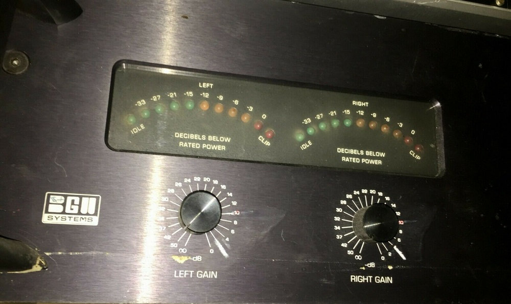
On a side note, once you have all the issues fixed, you will notice that when you bench test the amplifier, the "clip" LEDs will illuminate quite prematurely on either an 8 or 4 ohm load.
I noticed that when working on my new (literally) 750B myself. It is possible to get around that with a small modification to the LED board itself. The clip LED needs to be isolated from the rest of the display first of all. You will notice that there are two small unused 2 conductor connectors lying just below the potentiometers.
Those are part of the standard chassis wiring harness and made to light the clip lights on the model 750C. Those are the true clip indicators that illuminate at actual clipping.
You have a first generation 750B. Subsequent multicolor LED models made use of those clip indicators. The entire LED drive circuit was also revised to an IC driven display.
Attachments
This is a little off-topic, but does anyone know what the connectors on that VU meter board are called? They're used in lots of amps and I wouldn't mind stocking some spares (I have had a few fail), but for the life of me I can't find them.
Hello Michael,
yes I had seen these 2 connectors lying at the bottom of the chassis and I wondered what they could be used for, you just gave me the answer. this is a first version.
for that it will be necessary that I place a load of 8 ohms at the output, I have wound resistors which I think make 400W in total under 8 ohms. but I am not there yet because I have to finish replacing the LM318 and the 3 chemical capacitors which should arrive this week and check that I no longer have any leaks with the other tantalum and ceramic capacitors.
We have a problem in Belgium to get supplies because the goods come from UK (Brexit).
your clip leds will start clipping at whatever voltage you output?
I will try to when everything is in order to send a signal and turn up the volume and take the output voltages for each led level, as this will give us an idea of the whole.
for the moment I have not received my power supply for the PC fan that I have placed either and I am still wondering if I could not just resume on the view-meter power supply which is at 15Vdc. my fan consumes max 80ma. there is no information on this transformer winding except the fuse value of 1.5A / 240v, I will place my multimeter in series to see this consumption and finally define if I can use this for the PC fan.
Last edited:
This is a little off-topic, but does anyone know what the connectors on that VU meter board are called? They're used in lots of amps and I wouldn't mind stocking some spares (I have had a few fail), but for the life of me I can't find them.
are you talking about their connectors? because on my version I have two kinds.
a white 4 poles which goes to the sight-meters, except on the datasheet it speaks about 5 poles and it does not have the same shape as the Molex used on PC.
the 2 other small connectors are Brown with 2 poles and as Michael has just given the info it is for the adjustment of the clip leds.
That looks like an interesting project titoon.
On a side note, once you have all the issues fixed, you will notice that when you bench test the amplifier, the "clip" LEDs will illuminate quite prematurely on either an 8 or 4 ohm load.
I noticed that when working on my new (literally) 750B myself. It is possible to get around that with a small modification to the LED board itself. The clip LED needs to be isolated from the rest of the display first of all. You will notice that there are two small unused 2 conductor connectors lying just below the potentiometers.
Those are part of the standard chassis wiring harness and made to light the clip lights on the model 750C. Those are the true clip indicators that illuminate at actual clipping.
You have a first generation 750B. Subsequent multicolor LED models made use of those clip indicators. The entire LED drive circuit was also revised to an IC driven display.
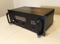
Your 750B looks like new, where you get this amp, new old stock ?
I love this amp
yes all later model have LM3915 LED driver IC but obsolete now
discrete circuit no problem to fix
Last edited:
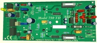
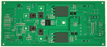
Preview BGW 750 B/C REBORN 2021
have nothings to do whole day due goverment Covid-19 lockdown + work ban
habe revised BGW 750 B/C
- Add: Balanced Input with Clip Limiter
- Original 750 B/C LM318 Input stage circuit
- Add: second stage cascoded, MJE 340/350
replaced with 2SC3503 / 2SA1381
- ADD: VBE replaced with IRF510
- ADD: BJT output Stage replaced with HEXFET / UNIFET
N-Channel Power Mosfets
- ADD: Triac Crowbar DC Protection
- ADD: Short Circuit and Overload Protection
- ADD: Turn On Delay / Off / Mute without relay
Extension: Class TD with additional driver board
without working Clas AB
Attachments
Your 750B looks like new, where you get this amp, new old stock ?
I love this amp
yes all later model have LM3915 LED driver IC but obsolete now
discrete circuit no problem to fix
Schönen Tag NMOS,
Great amps! It`s as close to New Old Stock as you`ll ever find I suppose. I started a thread regarded this particular amp here:
BGW 750B find | Audiokarma Home Audio Stereo Discussion Forums
N-channel mosfets aren’t necessarily any better for SOA than MJ15024’s. Especially new types. If you’re going to do this, use an older type which has been around since the dawn of time, and *isnt* optimized for low Qg and fast switching. The older types actually had decent DC SOA.
Schönen Tag NMOS,
Great amps! It`s as close to New Old Stock as you`ll ever find I suppose. I started a thread regarded this particular amp here:
BGW 750B find | Audiokarma Home Audio Stereo Discussion Forums
too bad you have to register to see all the photos :confus:
- Home
- Amplifiers
- Solid State
- BGW 750B output modules