You might try a couple drops of motor oil in the old fan, please leave the wd40 on the shelf and away from reciprocating parts.
Light oil, like 3-in-1. But chances are the bearings are shot if it is rattling. It could continue to run like that for years, giving you time to research a final solution. You’ll probably end up with a DC fan, turned down in voltage to keep it quiet. Then you have the option of kicking it up to full when needed.
I have a BGW 750B and have really enjoyed the information here. I made the C1, C3, C11, and C12 updates with upgraded capacitors and .1 uf bypass caps. My question is about the 47uf 100v bypass caps across the main filter caps that was suggested by djk. Are these are the 210000 uf 100v oil can sized capacitors? Can anyone confirm the improved bass due to this mod. Also, I could not find a pic of this particular mod, so is it a matter of discharging the capacitor and attaching the 47 uf leads to the 210000 cap in parallel? Thank you. Herb
hrp : what did you replace C3 with?
Thanks!
hrp : what did you replace C3 with?
Thanks!
C3 replace with new one Elektrolyt or 47 uf NON POLAR (recomended)
C1 with 2,2 uf 16 V NON POLAR
Wg_ski:
Malta: Thanks for posting the comparison of specs. It is good to hear you have had experience with these amps in a club environment! When complete my 750c will be powering midrange in JBL/Altec sound system. To clarify, I can use a 2.2UF 16V for C3 even though the original part is 50uF ?
J
Sorry Mistake
I mean C1 (not C3 ) 2,2 uf NON POLAR 16 V or similar n
Phase & Wg Ski
Thanks for the tips!! No WD40 ;-)
I actually spun it by hand as fast as I could and its was silent and smooth... maybe it't just catching on something when installed... will check that out too! But then what do I know! however I am learning Thank You!
Thanks for the tips!! No WD40 ;-)
I actually spun it by hand as fast as I could and its was silent and smooth... maybe it't just catching on something when installed... will check that out too! But then what do I know! however I am learning Thank You!
Hi. I used UKA1C470MDD1TD 47uf 16v bypassed with UKW2A0R1MDD1TD .1 uf 100v . I just did it last week and have not really tested it other than turning it on and making sure there was no magic smoke trying to escape. Maybe an expert can chime in on my choices and offer better options. Herbhrp : what did you replace C3 with?
Thanks!
HI NMOS3 Capacitor and 1 resistor is missing in D revision
please check schematic which parts missing und give feedback.
Did you have difference sound in Fullrange between D and C Revision ?
I couldn't really hear any difference between revision C and D, but I must admit that I didn't knew that there are mixed revision before I've started to recap them.
I agree that probably Audio1Man could further advise on this!?
I'm not sure if I should upgrade von C to D..
Hi. I used UKA1C470MDD1TD 47uf 16v bypassed with UKW2A0R1MDD1TD .1 uf 100v . I just did it last week and have not really tested it other than turning it on and making sure there was no magic smoke trying to escape. Maybe an expert can chime in on my choices and offer better options. Herb
0,1 NON POLAR !
Not electrolyt !
HI NMOS
I couldn't really hear any difference between revision C and D, but I must admit that I didn't knew that there are mixed revision before I've started to recap them.
I agree that probably Audio1Man could further advise on this!?
I'm not sure if I should upgrade von C to D..
Yes, he was BGW engineer and leave BGW 1985
than the new models come on the market for sale
All BGW Models from 1974 to 1985 are very reliable and working after decades very well (except BGW8000 - this amp used new design) can easy be fixed for back to life
The newer Models from 1985 up 750 D/E and F/G didn't have good sales
and can therefore hardly be found as used equipment and impossibile to
fix if fail.
Another major disadvantage of the new models >1985 is that they are not
repairable due to obsolete Japan components.
The models from 750 D / E - GTA - GTC
1. have a discrete front end, dual NPN Japan transistors used for this are obsolete, ONSEMI or TI no have anything for replacement to fix it
2. NEC or Sanken power transistors (BGW8000 - 750 D/E + 1 Genration 750 F/ G) are obsolete.
3. Due to NEC or Sanken power transistors design, pin assignment and mounting, TO 247 / TO264 / TO3P cannot be used as replacements in early design < 2002 sold models
These specially Sanken and NEC have been obsolete for a long time, NEC go out of Business long time ago
2002 BGW changed to TO3P in Revision A and B for 750 F/G GTA GTC
Chinese Eingineer Ming Shu make schematic and PCB changes in 2002 so that standard TOSHIBA and ONSEMI power transistors can be used, add improvements and fixed some design flaws
Last edited:
If your fan is noisy, a typical weight/grade of motor oil may help to quiet it down since there is now extra clearance between the moving parts that wasn’t there before.
This worked on an old Hafler amp I have.
This worked on an old Hafler amp I have.
Yeah the two new ones I have tried, make an awful wining noise, far more noticeable than the rattling of the old one! Crazy!?? Not cheap either. So I am hoping to return the new ones.
Yes in handling the old one, it does seem to move about more than it should, so yes thanks I will see if I have some motor oil somewhere!
I don't suppose it is is wise to put another 300 Ohm resistor in series with the other one?
Just to slow things down a bit, while the amp is not working very hard, when it warms up it will go into hurricane mode bypassing both resistors, and at that time one is quite likely not to notice the fan due to the volume of the music! Reasonable idea? or daft idea?
Thanks!!
🙂
Yeah the two new ones I have tried, make an awful wining noise, far more noticeable than the rattling of the old one! Crazy!?? Not cheap either. So I am hoping to return the new ones.
Yes in handling the old one, it does seem to move about more than it should, so yes thanks I will see if I have some motor oil somewhere!
I don't suppose it is is wise to put another 300 Ohm resistor in series with the other one?
Just to slow things down a bit, while the amp is not working very hard, when it warms up it will go into hurricane mode bypassing both resistors, and at that time one is quite likely not to notice the fan due to the volume of the music! Reasonable idea? or daft idea?
Thanks!!
🙂
I added a DC fan...it's very quiet now.
BGW 750C
Hi Guys,
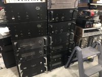
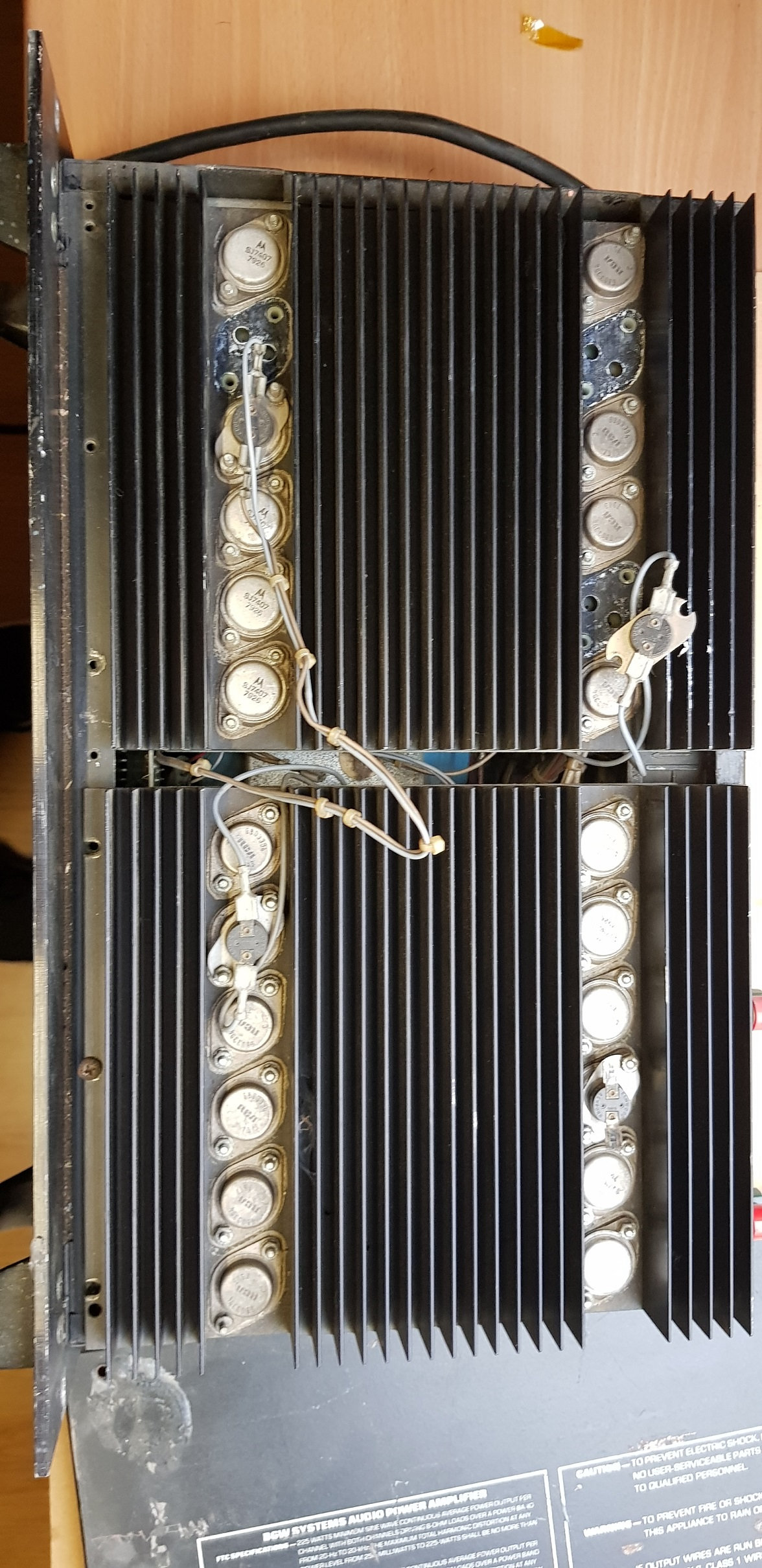
I think this might be my first post here. I have been active on AK for years. Last fall I acquired a bunch of BGW amps from an estate sale. I have been in the process of testing these starting with the B and C versions one of which did not pass the dim bulb test. I have done some reading on these and decided to get into this one. Both modules do not pass dim bulb test and will trip the breaker. One module I desoldered the outputs (A few were bad) and tested some of the other transistors which were fine. With the outputs out and the one module plugged in it does not trip the breaker. A few questions and please be patient as I am not real familiar with amplifiers and how they work.
With the output transistors removed I am getting between 60 and 80V at almost all the transistors on the board. I am trying to make sure I don’t cook more transistors. Am I going about this correctly?
What should I be replacing the outputs with? The standard OnSemi MJ15024/25 recommendation does not seem to be available or maybe it has been replaced with the same number ending in G?
Hi Guys,
I think this might be my first post here. I have been active on AK for years. Last fall I acquired a bunch of BGW amps from an estate sale. I have been in the process of testing these starting with the B and C versions one of which did not pass the dim bulb test. I have done some reading on these and decided to get into this one. Both modules do not pass dim bulb test and will trip the breaker. One module I desoldered the outputs (A few were bad) and tested some of the other transistors which were fine. With the outputs out and the one module plugged in it does not trip the breaker. A few questions and please be patient as I am not real familiar with amplifiers and how they work.
With the output transistors removed I am getting between 60 and 80V at almost all the transistors on the board. I am trying to make sure I don’t cook more transistors. Am I going about this correctly?
What should I be replacing the outputs with? The standard OnSemi MJ15024/25 recommendation does not seem to be available or maybe it has been replaced with the same number ending in G?
Attachments
Does anyone have a source for an AC fan that would be quiet? 2 of the 750 I am working on have noisey fans. One of them is very quiet. Seems like with the right fan the 2 speed fan set up is the right thing. I know some people are installing DC computer fans with a walwart for a power supply.
I’ve found that the best solution for fans in general is 24 volt DC fans, switching them down to 12 volts for lower speed. 24v fans seem to be beefier with better bearings than 12v “computer” fans which are designed to last a couple years and either quit or get noisy.
As far as what outputs to use? 15024/5. The G version is the same. More rugged than the 2119x in this particular application. Get the entire amplifier working without outputs (at all), driving a 100 ohm load correctly, then install the output banks.
As far as what outputs to use? 15024/5. The G version is the same. More rugged than the 2119x in this particular application. Get the entire amplifier working without outputs (at all), driving a 100 ohm load correctly, then install the output banks.
So, I think you are saying with outputs removed I should not be seeing the high voltage all over the place. I guess I will pull some more transistors and test them.
Funny just today I went through that whole stack in the photo and tested them all. Most have fan problems and need power cords but they all work!
Funny just today I went through that whole stack in the photo and tested them all. Most have fan problems and need power cords but they all work!
You will see high voltages - at the rails. With no output transistors you should see no DC at the output. That’s the first indicator you should look for. These amps will operate normally into a high impedance load directly off the drivers. If some sort of fault occurs in that state the damage will be minimal and can’t take a set of outputs with it. The worst that could happen is a shorted driver transistor, which will smoke the base-emitter resistors for the output bank but will not take out the other driver, if it’s good. The resulting fault current can’t get high enough to do anything worse than smoke a cheap resistor or two. You should still use a dim bulb limiter anyway - and if you run output-less the idle current will always be low enough to let the rails come up to near normal operation even if the bias pot is turned all the way up. You can also verify that before the outputs are even installed and make sure it starts turned *down* all the way when they are installed.
If the amps were all working, there is no real need to go through this exercise. It is what you do if it’s never been turned on and you just don’t know, or if you’re still tracking down faults and not sure if they are all cleared before putting in new outputs. The only thing really wrong with these designs is that shorted predriver stages or an open bias stack can blow entire output banks. These types of faults must be cleared first.
If the amps were all working, there is no real need to go through this exercise. It is what you do if it’s never been turned on and you just don’t know, or if you’re still tracking down faults and not sure if they are all cleared before putting in new outputs. The only thing really wrong with these designs is that shorted predriver stages or an open bias stack can blow entire output banks. These types of faults must be cleared first.
Good morning all,
I got a BFW750B from a friend but it was broken.
it was certainly opened by several technicians because some components are missing and others are damaged or broken on the left channel, the right channel seems to have nothing, but I have not powered it yet.
as it lacks transistors and broken or absent resistors, I will replace them of course: see the attached photo.
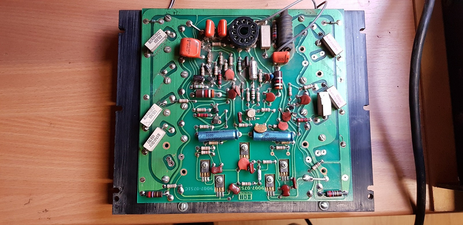
moreover there are other small transistors and condos which are also broken or damaged, we can see it by eye. I would like to restore it to use in living room mode only.
I will replace all output transistors with new ones of type MJ15024 and MJ15025, I think this must be the best at present as a replacement?
I have read different views on the fan and I wonder if we could not place a 12vdc 40ma PC type fan on it by plugging into the 15vdc output available with a zener to lower this voltage to 12vdc. I have a fan model which is available with 3 speeds under the Noctua brand which allows to vary the air flow as well.
before changing this, turn it back on first.
I downloaded the manual service, but there is no photo to identify the components by their number, no photo of the layout on the PCB.
Phil
I got a BFW750B from a friend but it was broken.
it was certainly opened by several technicians because some components are missing and others are damaged or broken on the left channel, the right channel seems to have nothing, but I have not powered it yet.
as it lacks transistors and broken or absent resistors, I will replace them of course: see the attached photo.


moreover there are other small transistors and condos which are also broken or damaged, we can see it by eye. I would like to restore it to use in living room mode only.
I will replace all output transistors with new ones of type MJ15024 and MJ15025, I think this must be the best at present as a replacement?
I have read different views on the fan and I wonder if we could not place a 12vdc 40ma PC type fan on it by plugging into the 15vdc output available with a zener to lower this voltage to 12vdc. I have a fan model which is available with 3 speeds under the Noctua brand which allows to vary the air flow as well.
before changing this, turn it back on first.
I downloaded the manual service, but there is no photo to identify the components by their number, no photo of the layout on the PCB.
Phil
hello,
I recovered a broken BGW 750B, missing output transistors on the Left channel and broken or missing resistors.also various other broken components. it was badly conducted.
i did not turn it on because it must have been broken for several years, so i have to gently re-energize it so as not to cause an electric shock, i have an autotransfo to try.
as the right channel seems to have nothing I will test it alone, it is advantageous to be able to remove each amp separately.
on this model there is not a lot of chemical capacitor, so I think replacing them all given the year of manufacture of this amplifier and relay board.
my use will be for home on hi-fi speakers, so on the forum we are talking about the noise of the fan which was intended for sound on the 4 ohm load, my use will remain on JBL E100 northbridge:
System type 3-way
Enclosure type Bass-reflex
Frequency response ± 3dB 33 - 20000 Hz
Nominal impedance 8 Ohm
Amplifier Requirements 125 W
Sensitivity (2.83V/1m) 91 dB
Tweeter 19 mm (3/4 in.)
Midrange 100 mm (4 in.)
Woofer 2 x 250 mm (10 in.)
Dimensions (H x W x D) 42.01 x 12.24 x 14.49 in.
Weight 25 kg / 55 lbs.
So I thought I could replace the 110vac fan with a 12vdc 40ma PC fan that would dump its current on the 15vdc available for the LED view meters and decrease its voltage by a zener to 12vdc, shouldn't that cause a problem?
but the main thing for the moment is to repair the whole Left channel with MJ15024 and MJ15025 and replace the other broken components.
I downloaded the manual service, but there is no photo to identify the components by their number, no photo of the layout on the PCB.
- Home
- Amplifiers
- Solid State
- BGW 750B output modules