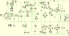
Have redesigned Original 750B and add some circuits from Class D design to 750B
LM 318
VAS cascoded KSA 1381/KSC 3503 with BC
Driver Toshiba TTA
Output stage N-Channel Mosfets IRFP360/460 or FDA69N25
Limiter
Short circuit and delay turn on without thumps
DC Protect Crow Bar
LM 318
VAS cascoded KSA 1381/KSC 3503 with BC
Driver Toshiba TTA
Output stage N-Channel Mosfets IRFP360/460 or FDA69N25
Limiter
Short circuit and delay turn on without thumps
DC Protect Crow Bar
Attachments
Last edited:
Thanks for the reply guys. The power amp module I have has all Motorola SJ7407A on one side and RCA 6803394 on the other. They appear to be all original.
I was able to trace the circuit to the online schematics and looks like whoever butchered it before attempted to make the D version of the board into the E version by adding a 100 ohm resistor to the base of Q8 and similarly for Q9 along with the 1000pF bypass caps.
The collector of Q9 was also disconnected from the collector of the first power transistor Q10. This just seems wrong.
My plan is to fix all the trace issues so it matches the online schematic.
Make me want to look closer at the version B board and figure out what is going on there.
I terms of upgrade, my plan is to simply swap all of the lytics to newer ones, swap c10 with a PP type and add bypasses to the PS caps as suggested in other 750c threads. I dont have the skills to redesign this as some of you experts have done.
Last edited:
Does anyone have a first generation 750B schematic? That would be the one with all red power level LEDs.
The schematic I have on hand I believe was sourced from HiFi Engine which is for the newer multi-color LED model and does differ slightly.
I just finished up a repair on my amp that decided to go supernova on me for no apparent reason. A few output and driver transistors died as well as a few upstream transistors. Most of the emitter resistors too were open and also some smaller 1/2w and 2w.
The relay contact on the bad channel fused in the on position and melted the trace on the relay socket.
I replaced all the driver and output transistors with MJ21195/96 and had to use a substitute 2N4923 for the MJE720.
The real mystery here was the value of R52, one of the resistors that failed. What was mounted on the amplifier was 180 ohms but according to the schematic, is listed as 1.8K. Im guessing that value was revised in subsequent versions of the amp but I would like to know if what is in there is correct.
It`s all good now, very good actually. 278wpc@7.5R, 1kHz both channels driven just below clipping and 880w@7.R in mono.
Attachments
R22 Bias AdjustDoes anyone have a first generation 750B schematic? That would be the one with all red power level LEDs.
The schematic I have on hand I believe was sourced from HiFi Engine which is for the newer multi-color LED model and does differ slightly.
I just finished up a repair on my amp that decided to go supernova on me for no apparent reason. A few output and driver transistors died as well as a few upstream transistors. Most of the emitter resistors too were open and also some smaller 1/2w and 2w.
The relay contact on the bad channel fused in the on position and melted the trace on the relay socket.
I replaced all the driver and output transistors with MJ21195/96 and had to use a substitute 2N4923 for the MJE720.
The real mystery here was the value of R52, one of the resistors that failed. What was mounted on the amplifier was 180 ohms but according to the schematic, is listed as 1.8K. Im guessing that value was revised in subsequent versions of the amp but I would like to know if what is in there is correct.
It`s all good now, very good actually. 278wpc@7.5R, 1kHz both channels driven just below clipping and 880w@7.R in mono.
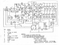
R24 DC offset
I hope you check all is fine or readjust resistor value
2N4923 for the MJE720
BD139, BD437 work fine
BC546 recommended
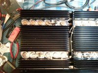
I rebuilt and modified a 750B for hi-fi and one for PA, added input XLR buffer with clip limiter in front of the LM318 IC and Solid State DC Protect Triac Crowbar, overcurrent protection without the original circuit breaker, manual DC Offset Adjust
2 pairs of FDA69N25 N Channel Mosfets replace all 12 TO-3 transistors per channel without any problems in PA use for several years */- 70 V DC
Advantage: hardly noticeable heating of the heat sinks due to the quiescent current in standby compared to the bipolar TO-3
Clarity in the sound which was not technically possible with the old, slow hometaxial transistors.
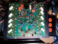
I just repaired a 750A that my neighbor picked up. I wanted to say thanks for this thread that helped me and also share a few notes...
I saw the same physical damage as titoon showed in his pictures earlier in this thread (#346). I found that the power transformer had speednuts on the bottom lugs. It makes sense since you could not possibly get a regular nut and lock-washer there. However, both screws were missing at the bottom of the transformer and I believe it swung on the top pair of screws into the circuit board. Hammered it over and over in transport. I found that the op amp was broken off of most of its pins, caps were torn off their axial leads, and the large resistors were pushed through the solder so that they were loose in the trace. I've never had to do this before, but I had to go through all the larger components and refresh their solder joints. I would recommend putting some loctite on those bottom screws - especially if the amp is being gigged.
I also think that the missing screws on the transformer went undetected because the circuit board with the stereo-mono switch was an older generation (no solder mask) and the one that was destroyed over the transformer was newer and different (and had a solder mask). So I suspect that the circuit board over the transformer was broken and replaced at least once before. The older one was labeled HS1751B and matched the schematic below from the manual you can find on hifiengine. The other board was labeled 9007-0750 and was different. It was still quasi-complimentary, but had some minor differences. I've attached some rough notes to capture that to this post.
First note that some component values on the schematic were updated in the parts list. The parts list matched my older physical board.
On the newer board I found several components missing. Circled on the schematic, I did not find C9, R9 or C17. There was also additional protection. There was a diode and zener anode-to-anode from the output to the base of Q4. This zener had changed value and needed replacing. I was able to read 1N4729 on that part. There was also an additional TO-18 NPN transistor that I could not read a part number from. It's collector was on the negative rail. The base was connected to a voltage divider between the base of Q7 and the negative rail. Those resistors there are 22K and 10K. Finally, there is a 30 ohm resistor between the emitter and the base of Q2.
I also want to say thanks again for the comments in this thread. Because I read that the fan ran low and high, I discovered that the low speed resistor had blown out. Seems that the wiring for the thermal switches had been pinched between the fins and cover at some point and killed the resistor. I found a tell-tale notch in the fins where that happened. Since my neighbor was looking for a consumer application, I replaced that resistor with 470 Ohms and got a fairly quiet result.
So thanks for all your comments, and I hope this post might help someone along the way.
Attachments
Hi dadr,
C17 is an HF compensation component. When the design changed they didn't need it anymore. Also, you will find on many older amplifier designs, the type of output transistors would affect he value of the HF stability components (compensation). This is still true in current amplifier designs, but the older output transistors varied a great deal in HF characteristics.
As a guess, R9 and C9 provided a more even load for the LM318. It's entirely possible the LM318 changed in design makin that unnecessary. That's a complete guess on my part, but back then parts might change without any notice or change in part number.
I wouldn't own a 750A, the 750C is a pretty good amplifier with modern output transistors. Still, the 750A should be very reliable and might be alot better than other era amplifiers.
-Chris
Hello friends,
I'm trying my luck because it's almost Christmas, I've been looking for 4 SJ7407 transistors for a long time to finish repairing my BGW 750C could someone provide me with some? That would be wonderful.
Merry Christmas.
Freddy
I'm trying my luck because it's almost Christmas, I've been looking for 4 SJ7407 transistors for a long time to finish repairing my BGW 750C could someone provide me with some? That would be wonderful.
Merry Christmas.
Freddy
Hi dugain,
Which transistors are these? Every single transistor used in these amplifier have modern equivalents. I have rebuilt many. I don't feel like digging through the manual to figure out which they are.
If these are output transistors, you need to replace the entire set in that channel if any are blown short. I would use the MJ2119x series transistors and they work exceptionally well as they are greatly improved over original parts.
-Chris
Hello Anatech, this is an output transistor, actually, I would have liked to keep the initial configuration, not being a sound system but an audio listening experience that I found very good before the problem.
I do not know the sound of the new transistors in audio listening
I am a feedback taker.
freddie
I do not know the sound of the new transistors in audio listening
I am a feedback taker.
freddie
New ON MJ2119x do not SOUND any different than the old house numbered Motorola parts, which were selected 2N3773/6609. They just graded them for vceo, since it was above ratings. Everything about them which affects the SOUND is substantially the same. You just don’t want to mix old and new types in the same parallel bank.
Thank you for your answer and opinion on the on2119X
In my case the pair of output transistors is 7394/7407 changing everything to three transistors is really a shame but if it's the only solution maybe I'll do it.
In my case the pair of output transistors is 7394/7407 changing everything to three transistors is really a shame but if it's the only solution maybe I'll do it.
If the only bad ones are PNPs you just need the 21195’s. You could leave the original NPNs in the upper bank, as long as all the PNPs are the same. Old and new just can’t be paralleled.
OK I understand 21195 and 7407 are similar and so 21195/7394 complementary. Hope the sound is similar as original couple.
In this cas I need only 6x 21195.
Kind regards
Freddy
In this cas I need only 6x 21195.
Kind regards
Freddy
What did you do to the Model 100? I have one on the workbench now.replace LM318,
1 x BGW Model 750B
1 x BGW Model 100
LM318 failed after many years trouble free working
@ Audioman1 / Duke
Be careful when replacing the output transistors with new devices as the old > parts are HOMETAXIAL slow and the current parts are FAST
Yes, but when change to fast todays devices you get clarity in sound a huge improvement
When even one output transistor fails, you replace the entire set. Especially if the new parts are not the exact same as the old ones. One reason is that say a PNP shorts, that's like a wire to the negative supply (normally) and forces all teh NPN devices to conduct more than their rated current, or at least a couple. If they don't outright fail it often changes their characteristics. In any event, that channel will often fail later. I also replace the driver transistors for the same reason.
Nope, the transistor won't change the sound. However a matched set can reduce distortion. I've seen this empirically over many years. Measured results. The MJ2119x series does have a flatter beta vs Ic curve, meaning at higher currents they will not suffer as much gain droop and that can affect preceding stages and lower distortion at higher power levels. They also have better processes and more will match in beta (higher yield when matching from a population of parts). So the newer parts are in fact better from a couple of viewpoints.
Fresh grease and insulator mica - please! Do not overtighten the outputs or drivers when installing them.
-Chris
- Home
- Amplifiers
- Solid State
- BGW 750B output modules