BTW, Whisky's on me next time. Thanks for the help and sorry I'm old and slow
Good gosh, no need for apologies. We all learn and process information differently. I should be more concise. 😀 I'm sorry I was short with you and bailed out earlier. I had to run to dinner and was late.
So happy it worked out and nothing was damaged. 🙂
re: c7. Those are often discussed. I don't delve into that. Search for bypass caps, and let your mind go free. 🙂 Others may have a strong opinion and reasoning for their choices they can share.
I know nothing about crossover design, so I can't answer your exact question.
I'll just say it this way. I didn't use them in my Aleph J build. I've used bypass caps in other builds. Some people swear by them. I'm impartial.
I think both choices are wonderful choices. It's a hobby. If you have them already, toss them in. If not, you can always add them later if you want to see if you can hear the difference.
Get out your shorty Phillips head screwdriver and loosen (just a little!) the bolts that hold the brackets to the heatsinks.
With them loose, now line up the bottom cover and attach it.
Do your best to square up the top, when the holes all line up, snug the brackets bolts and put the top plate on.
The entire chassis bolts into the brackets. They are the spine that holds it all together. It's not immediately obvious that's how it works, but the good thing is that it's easy enough to align.
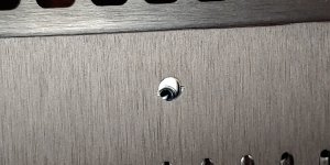
Great advice, and I used this technique a few times to get all the other bits to align, but it was to no avail for the bottom cover. The chassis base plate is just a little too wide, and no amount of fiddling with the rails was going to make it narrower. The fact that the chassis base plate to rails connection is countersunk makes it impossible to nudge that narrower.
Fortunately, drilling out all four holes in the bottom cover to be just a little bigger was enough to do it, and the plastic feet cover any sloppy drill work. 🙂
Attachments
Mkane77g - Just leave them empty. Not required, next aleph PCB probably Won’t have them.
Rye. Nice. 😀

Rye. Nice. 😀
Great! So you have about 25 Vdc on both outputs of the PSU and both channels LED is lit I take it?It work's . Passed DBT. 25VDC both sides. I take it one side gets wired backwards to get -25VDC?
Use 22k for R9 and R10 of the PSU later. The bigger the value of the resistors in this place, the higher the power dissipation, meaning it will bleed the cap banks of its voltage faster when you turn the amplifier Off.
Actually it is the opposite. A larger value of bleed resistor will slow the bleed. However, that only matters when there is no load on the power supply, other than the bleed resistor. Once the amplifier boards are connected to the power supply, the current draw is much higher than the bleed current so the capacitors will drain in a very short time.
Also a 2.2K bleed resistor only drains about 10 or 11mA so not much current is lost. So no need to change the bleed resistor to 22K.
Also a 2.2K bleed resistor only drains about 10 or 11mA so not much current is lost. So no need to change the bleed resistor to 22K.
Ah yes, you are correct. My mistake.
To select a suitable bleeder resistor, you can consider the relationship between the momentary voltage across the capacitor Vt, the bleeder resistance R for discharge, the initial voltage Vu. t is the momentary period and the total capacitor capacitance is C. Then, you can use this equation to estimate the required value of your bleeder:
Vt=𝐕u x 𝒆^(−𝒕/𝑹𝑪)
There is always a trade off between the speed the bleeder works at and the amount of power waste in the bleeder. Lower values of bleeder resistance will give you a faster time to reach safe voltages when the device is powered down, but they will also waste more power during operation.
The bleeder resistor R should have a value high enough so that it does not interfere with the operation of power supply, but low enough so it will discharge the capacitor C, in a short time after the power supply has been shut down.
And only 1.13 mA with 22K resistor. If it is me, I will change it.Also a 2.2K bleed resistor only drains about 10 or 11mA so not much current is lost. So no need to change the bleed resistor to 22K.
Last edited:
Your bleed resistors are incorrect. You have 0.47R, which are acting as shorts to ground. They should be much higher value, say anything over 2K Ohms and 3W or higher.
I am surprised that fuses have not been blown, or the resistors burned up. Perhaps your rectifiers have been toasted because of the large current due to the low value bleed resistors.
This did the trick I take it?
The LED on the left side is not on even though there's 25VDC. I'll replace it.
Is there a reason some use the rectifier bridges vs using the transistors with heatsinks? Is it just a space issue.
Would it be ok if I mounted those bridge rectifiers to the large heatsinks?
I'm going to continue with this today while my wife's away. I started this build in 2017 but got caught up in the tube amp rabbit hole.
Attachments

Last edited:
6L6 thanks. Waiting for your wiring section
Don't pay attention to my wiring comment, it was aimed at the fells documenting the noobs thread.
LED is probably in backwards, not inoperative.
Yes, you could mount the bridges to the main heatsinks.
The bridges on the PSU are better diodes, already heatsinked, and most importantly, working properly... why change it?
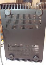
Get an L bracket for the transformer if you want more room on the chassis floor.
Yes, you could mount the bridges to the main heatsinks.
The bridges on the PSU are better diodes, already heatsinked, and most importantly, working properly... why change it?
Get an L bracket for the transformer if you want more room on the chassis floor.
Replace and/or potentially just reverse. Make sure polarity is correct. Covered in the guide.This did the trick I take it?
The LED on the left side is not on even though there's 25VDC. I'll replace it.
Increased space, increased cost, added build complexity are some potential negatives for discreet. Potential for better PSU performance is a positive. Some people have their favorite diodes.Is there a reason some use the rectifier bridges vs using the transistors with heatsinks? Is it just a space issue.
Some (or maybe all) of the commercial First Watt amps use monolithic bridges if that matters to you 😀
For your purposes, I'd recommend saving the discreet sections you've already removed for another build. You have it working.
Would it be ok if I mounted those bridge rectifiers to the large heatsinks?
Yes, but you'll be adding to the heat load on the main sinks right next to one of your output parts. Plus the wiring distance may be something that could bite you re: noise. People have mentioned to me and others that keeping AC runs as short as possible and away from I/O is a plus.
The chassis floor is likely a good option. Since you are now closer to the build guide configuration, I'd give it a look if you have not. It is excellent, and that's what this thread is for. Give it a glance, see where you have questions, and let the OP know what is crystal clear, and maybe what could be clarified.
I'm going to continue with this today while my wife's away. I started this build in 2017 but got caught up in the tube amp rabbit hole.
Have fun!
Edited to add - Clearly I need to be more concise. 6L6 already answered while I was typing. I thought you removed the diode section from your boards and were now using the monolithic, so you were asking re: where to mount them. If that's not the case, use what you have working.
Last edited:
I did remove the diode section and why I asked about mounting bridge rectifiers to the heatsinks. I'm thinking I'm going to use the diode section.
And now looking at the multi turn pot's, is there a way to test without power to be sure there in the ballpark? I've looked at the build notes and can't find anything.
And now looking at the multi turn pot's, is there a way to test without power to be sure there in the ballpark? I've looked at the build notes and can't find anything.
mkane77,
Yes, your main problem was that you had 0.47R installed as bleed resistors. That most likely caused your initial powerup problems when you had the discrete diode rectifiers installed on the PS board. The extreme current draw was due to the short caused by the 0.47R bleed resistors and that blew the fuse.
When you replaced the fuse and powered up again, nothing happened. With the 0.47R bleed resistors still in place the fuse should still blow. So it was likely that the bleed resistors were blown by the first powerup. You can check the 0.47R resistors that you removed. Measure their resistance.
Edit: Blown bleed resistors would not account for the extremely low voltage output after the first blow-up. If the resistors were blown open, the short would no longer exist and if everything else was still functional, the power supply should have produced the correct voltage. It did not, so the discrete rectifiers are suspect, or a wiring error, as when you changed rectifiers and installed the correct value bleed resistors, the PS worked properly.
Since you also removed the discrete diode rectifiers and replaced them with the monolithic rectifier blocks, also check them with your meter using the diode check function. It is possible that they may have been damaged by the extreme current.
I also suggest you do not change the bleed resistors from 2.2K to 22K. The 22K will take a really long time to drain the capacitors should the need ever arises. The 10mA draw of the 2.2K is inconsequential compared to the current draw of the amplifier boards. 22K is usually recommended for much high power supply voltages.
Last edited:
And now looking at the multi turn pot's, is there a way to test without power to be sure there in the ballpark? I've looked at the build notes and can't find anything.
6L6 gave the straight, short answer.

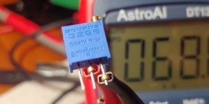
If you want to make sure the trimpots are what they're supposed to be (for example 200K), look at their mark on the body and/or measure them).
If you already played around with them, and want to be sure they're not at a bad position, turn them to the end (until they block) and turn them back 12 full rounds (assuming they're 25-turns)...
https://www.bourns.com/docs/product-datasheets/pv36.pdf?sfvrsn=87259ff1_14
Edit: I just went to see if the marking returned a useful information—it's not that easy... Best is probably to measure them...

Last edited:
Edit: I just went to see if the marking returned a useful information—it's not that easy... Best is probably to measure them...
How to measure the pots, from my n00bs guide:
"When you get to the potentiometers (R7 and R27), make sure to set them to the correct value before soldering them in. For R7, it should be 1k ohms; for R27, it should be 68k ohms. To measure and adjust their resistance, you'll want to put the negative lead of your multimeter on the lead marked #1 (one of the "ends") and the positive on the middle lead, marked #2 (the "wiper"). Then turn the potentiometer screw until you get the desired reading."
Attachments
- Home
- Amplifiers
- Pass Labs
- Aleph J build guide for noobs