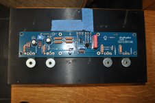
One problem: the holes on the bottom cover don't quite line up with the holes in the heat sink rails. I probably will have to drill the bottom cover holes out until the screws can see the holes. Sigh. There's always something.
Unplug the amp.
Get out your shorty Phillips head screwdriver and loosen (just a little!) the bolts that hold the brackets to the heatsinks.
With them loose, now line up the bottom cover and attach it.
Do your best to square up the top, when the holes all line up, snug the brackets bolts and put the top plate on.
The entire chassis bolts into the brackets. They are the spine that holds it all together. It's not immediately obvious that's how it works, but the good thing is that it's easy enough to align.
^^^^^ 
Until I was given this advice, my first chassis gave me FITS. I believe I may have used some strong language.
I recommend adding it to the guide.
Until I was given this advice, my first chassis gave me FITS. I believe I may have used some strong language.
I recommend adding it to the guide.

Just on the weird off chance.... you're not using an LED bulb are you?
I really, really want to see you get this going. You've put so much effort in. Fantastic folks are still chiming in, but I really have to head out, and following one set of instructions will make things much easier for you.

I really, really want to see you get this going. You've put so much effort in. Fantastic folks are still chiming in, but I really have to head out, and following one set of instructions will make things much easier for you.
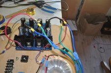
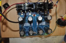
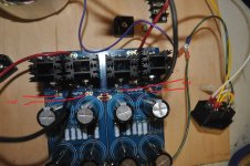
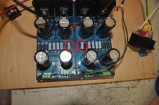
Pics showed wiring looks good.
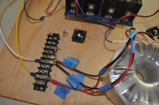
At this point, I will try a bridge. I will cut the links from the rectifier board to the cap bank (jumper wires) for both channels. Connect ~~ of the bridge to Grn and Blu secondary wires of the transformer. Connect + from the bridge to D+1 (or D++1) and - from the bridge to D--1 (or D-1). Do the same for the other channel. Turn power On. is LED lit? Output voltage (DC) at V+ (or V++) to Gnd and V- to Gnd?
At this point, I will try a bridge. I will cut the links from the rectifier board to the cap bank (jumper wires) for both channels. Connect ~~ of the bridge to Grn and Blu secondary wires of the transformer. Connect + from the bridge to D+1 (or D++1) and - from the bridge to D--1 (or D-1). Do the same for the other channel. Turn power On. is LED lit? Output voltage (DC) at V+ (or V++) to Gnd and V- to Gnd?
Rechecked ACV at both spots and I still have 19.2VDC
Measure Vdc on the other side of the rectifiers please.
Attachments
Measure Vdc on the other side of the rectifiers please.
I'm on it
Your bleed resistors are incorrect. You have 0.47R, which are acting as shorts to ground. They should be much higher value, say anything over 2K Ohms and 3W or higher.
I am surprised that fuses have not been blown, or the resistors burned up. Perhaps your rectifiers have been toasted because of the large current due to the low value bleed resistors.
I am surprised that fuses have not been blown, or the resistors burned up. Perhaps your rectifiers have been toasted because of the large current due to the low value bleed resistors.
Attachments
Last edited:
Pics showed wiring looks good.
At this point, I will try a bridge. I will cut the links from the rectifier board to the cap bank (jumper wires) for both channels. Connect ~~ of the bridge to Grn and Blu secondary wires of the transformer. Connect + from the bridge to D+1 (or D++1) and - from the bridge to D--1 (or D-1). Do the same for the other channel. Turn power On. is LED lit? Output voltage (DC) at V+ (or V++) to Gnd and V- to Gnd?[/QUOTE
I have 25VDC on both sides.
It work's . Passed DBT. 25VDC both sides. I take it one side gets wired backwards to get -25VDC?
Last edited:
Fantastic news! 🙂
Nope.
V- to GND (red probe on V- black on GND) should be -25VDC
V+ to GND (red probe on V+ black on GND) should be +25VDC
Edit - "Nope" in reply to the wiring backwards question.
Nope.
V- to GND (red probe on V- black on GND) should be -25VDC
V+ to GND (red probe on V+ black on GND) should be +25VDC
Edit - "Nope" in reply to the wiring backwards question.
BTW, Whiskey's on me next time. Thanks for the help and sorry I'm old and slow.
Attachments

Last edited:
- Home
- Amplifiers
- Pass Labs
- Aleph J build guide for noobs