I'm building a FW F4 and am using this transformer:
https://www.antekinc.com/content/AN-5220.pdf
I found these when I searched for the parameters you mentioned and then added the two lowest ESR values. The data sheet shows ripple current. but I don't know what I'm looking at.
https://www.tdk-electronics.tdk.com/inf/20/30/db/aec/B41505.pdf
https://www.antekinc.com/content/AN-5220.pdf
I found these when I searched for the parameters you mentioned and then added the two lowest ESR values. The data sheet shows ripple current. but I don't know what I'm looking at.
https://www.tdk-electronics.tdk.com/inf/20/30/db/aec/B41505.pdf
Last edited:
Alan - any of these will work beautifully;
https://www.mouser.com/Passive-Comp...Z1z0vn3sZ1yx4atvZ1ypb2ikZ1yx4avv&Ns=Pricing|0
https://www.mouser.com/Passive-Comp...Z1z0vn3sZ1yx4atvZ1ypb2ikZ1yx4avv&Ns=Pricing|0
Thanks. One of them is a stand out with 0.013 Ohms ESR. That seems very low. 4.69A ripple current.
https://www.mouser.com/ProductDetail/Vishay-BC-Components/MAL225650223E3?qs=9jMkQ3H923INeQSyS1H9iQ==
They're 22,000uF instead of 15,000.
https://www.mouser.com/ProductDetail/Vishay-BC-Components/MAL225650223E3?qs=9jMkQ3H923INeQSyS1H9iQ==
They're 22,000uF instead of 15,000.
Last edited:
What 6L6 said. I am using these for a class A amp with a 2x20 VAC Antek: 380LX333M035A052 Cornell Dubilier - CDE | Mouser
(I think they incorrectly show blue as the color - the ones I got were black, not that it matters) They are only $5.58 each in quantities of 10.
Each rail has 4 in a CRC arrangement. I used the DIY Store CRC boards, minus the rectifier sections, opting for monolithic chassis mount bridges instead.
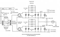
Attached is a schematic with part numbers and values which you may find helpful.
Cheers
(I think they incorrectly show blue as the color - the ones I got were black, not that it matters) They are only $5.58 each in quantities of 10.
Each rail has 4 in a CRC arrangement. I used the DIY Store CRC boards, minus the rectifier sections, opting for monolithic chassis mount bridges instead.
Attached is a schematic with part numbers and values which you may find helpful.
Cheers
Attachments
Regarding CRC Filtering
Hi,
R5-R8 and the three optional resistors form a CRC filter. The recommended values give an effective resistance of 0.1 to 0.25 ohms.
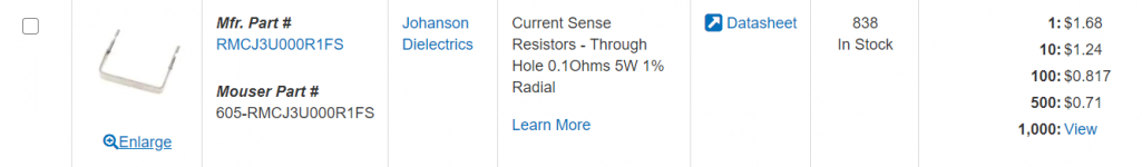
Is there any compelling reason to use flame proof resistors rather than an similar resistance shunt as shown below? I don't see why there would be a difference but I'm acutely aware that I often do not know what I do not know. 😀
Johanson Dielectrics Shunt Resistor (Mouser)
Hi,
R5-R8 and the three optional resistors form a CRC filter. The recommended values give an effective resistance of 0.1 to 0.25 ohms.
Is there any compelling reason to use flame proof resistors rather than an similar resistance shunt as shown below? I don't see why there would be a difference but I'm acutely aware that I often do not know what I do not know. 😀
Johanson Dielectrics Shunt Resistor (Mouser)
Attachments
If you're good with arithmetic you could calculate the body temperature of the resistor(s) in the two options, and see whether they differ by enough to be concerning.
Watts = current * current * resistance
Body temperature = air temperature + (watts * thermal resistance)
Watts = current * current * resistance
Body temperature = air temperature + (watts * thermal resistance)
Thank you for steering me in the right direction Mark.
Now I know that I have 2 equations and 3 unknowns. I'll work to resolve that deficiency.
Now I know that I have 2 equations and 3 unknowns. I'll work to resolve that deficiency.
I may not be able to help all that much, but here are a few things that cross my mind re: above. I know it's not what you asked specifically re: flame proof vs. current sense type, but there are potentially other considerations separate from temperature alone.
1) If your ultimate goal was to have 0R1 for each supply (V+ and V-), you'd be substituting a single resistor with full current through it for the 'normal' 4 and up to 7 resistors sharing current, I think. With a single 5W rated resistor vs. n*3W resistors, it may be a consideration.
2) You should potentially model the circuit with a single 0R1 to see if you get the smoothing you want / expect vs. whatever values you were considering of other types. Definitely an area I do not have a full grasp on.
3) The current for the equations above would (possibly) be the total bias current for your amplifier, if it's a Class A amp. You didn't mention the amp or configuration, so there's no way for us to really know how much current => power => heat you'd be subjecting the parts to. That would be under normal operation. If you were doing a BA with 12 devices per side @0A25 per device and using a single PSU => 6A total. That may not be great. I also think that the circuit / board designers considered other potential fault situations separate from normal operation that could subject those parts to higher current and the failure mode of the parts. I recall Mark (in another thread) observing possible temperatures for a part that could potentially even melt the solder (and most definitely cause harm if touched) even though the operating parameters were fully within the capabilities of the part. That ties back to your original question.
4) I can't find the exact reference, but there has been a lot of discussion re: the properties of the 'Blue Panasonic' resistors separate from their resistance, power rating, thermal characteristics, and failure modes. They seem to be an excellent part due to at least one other design property that escapes me. I just know that I've read that other similarly rated parts (at least in those few characteristics I've listed) may not perform as well.
Those are just a few things coming from a noob that may tie into your decision. I could be completely wrong on all of them. Your question interested me, so I tried to think it through as if I were in a similar situation at my current level of understanding. I always wonder what parts matter most in a circuit and why they're recommended / chosen for certain properties. Others with far more knowledge and experience will surely chime in. If you reach a conclusion, I'd enjoy learning more.
Hello,
When do you want to use and not use the Pi resistors for CRC filtering?
Thank you,
David.
When do you want to use and not use the Pi resistors for CRC filtering?
Thank you,
David.
This may help. Page 6 or so - "choosing your resistors".
https://www.diyaudio.com/media/build-guides/diyaudio-psu-build-guide-v1.0.pdf
https://www.diyaudio.com/media/build-guides/diyaudio-psu-build-guide-v1.0.pdf
This may help. Page 6 or so - "choosing your resistors".
https://www.diyaudio.com/media/build-guides/diyaudio-psu-build-guide-v1.0.pdf
I don't understand this statement,
" For Class AB amps, I personally like to make it just a capacitor bank style CRC filter without the PI resistors so I replace the resistors with a jumper wire."
I thought it was the Pi Resistors that made it a CRC filter?
David.
Exactly what is your question? Can you be more specific?
In post 1432, you ask "When do you want to use and not use the Pi resistors for CRC filtering?" The answer to that question using R=pi resistors, would be; you always use them. If you take out the 'R', it's not a CRC filter. 🙂
In post 1432, you ask "When do you want to use and not use the Pi resistors for CRC filtering?" The answer to that question using R=pi resistors, would be; you always use them. If you take out the 'R', it's not a CRC filter. 🙂
From the Build Guide,
"For Class AB amps, I personally like to make it just a capacitor bank style CRC filter without the PI resistors so I replace the resistors with a jumper wire."
If you are building the Universal Power Supply Board without the Pi resistors, replacing them with jumper wires, is it still a CRC filter?
"For Class AB amps, I personally like to make it just a capacitor bank style CRC filter without the PI resistors so I replace the resistors with a jumper wire."
If you are building the Universal Power Supply Board without the Pi resistors, replacing them with jumper wires, is it still a CRC filter?
Looks like a typo and JoJo most likely meant “CC” filter.
Obviously, if you remove the resistors it ceases being a “CRC” filter.
Obviously, if you remove the resistors it ceases being a “CRC” filter.
Looks like a typo and JoJo most likely meant “CC” filter.
Obviously, if you remove the resistors it ceases being a “CRC” filter.
Okay, thank you!
When you are a total noob and reading "The Guide" on how to use something and it doesn't make sense, I hope you can understand my confusion... 🙂
David.
Great question. Now I understand. Someone with far more knowledge than I would need to chime in re: whether that's a typo or if the 'R' in the CRC comes from another part of the circuit and/or if it's just a matter of semantics I don't yet grasp.
From what I can tell from the build in the linked guide, I don't see any pi resistors in the build on the boards with the green LEDs. I see the bleeder, the LED resistor, and the snubber resistor.
It looks like the boards with the red LEDs have the pi resistors.
Sorry that I can't provide more substance.
Edited to add - 6L6 to the rescue!!!!
If you're talking about the two sets of diode pads, it's just to accommodate different diode package sizes.
- Home
- Amplifiers
- Power Supplies
- diyAudio Power Supply Circuit Board v3 illustrated build guide