Use PSUD!
I think this has been mentioned before in this thread, but it bears repeating for those who wish to really dig into power supply design, capacitor selection, R, selection, etc.: check out @duncanamps excellent PSUD utility: PSUD 2.10 released
It is also available for macOS: PSUD2 for Mac released
The main issue I had with it was figuring out appropriate values for transformer impedance, but you can often infer these from manufacturers' specs for voltage droop vs. load (this is a simplification of course, but it gets you in the ballpark).
Hi, I am building the PSU and the build guide is confusing about the diodes, it shows cutting the center leg off and moving the legs to fit two holes. I have the mbr 20200 which has three legs, does it not install in the three designated holes? Thanks Don
I have the same diodes and my question the same? Thanks
I'm a little surprised that somebody took that as "cutting the center leg off", which is most certainly not what's happening. Those were merely 2-leg diodes.
Anyway, the MBR20200CT is a 3-leg, cathode center leg diode. Install all three legs just like you think they should.
Anyway, the MBR20200CT is a 3-leg, cathode center leg diode. Install all three legs just like you think they should.
Is it the general consensus to leave the Pi resistors out and replace them with jumpers for class AB amps?
Specifically, it is going to be for the LJM L20.5 amplifier board.
Specifically, it is going to be for the LJM L20.5 amplifier board.
AFAIK it is more that you don’t really need such effective ripple filtering in AB amps since current draw (and ripple) is dependent on amp output, whereas in class A current draw is high and more or less constant.
I built this PSU for use with a BA-3. while it works well in most aspects, I do have a slight audible hum in the speakers, and my troubleshooting leads me to believe it might be a common impedance issue.
I have been searching the threads, looking for the «ultimate» ground solution for this PSU.
What, in your experience, is the ultimate way to ground this thing? I am speaking of which of the ground links to put in, and where to make the star or T. Like 6L6 in the psu build guide, or is it OK to use the euroblocks? I am currently using euroblocks.
Cheers,
Andreas
Remember that (4) 0.47ohm 3W resistors in parallel is equivalent to a 0.12ohm 12W resistor.
My use case is an F4 amp and using the nominal F4 specs, the dissipation will be 3 watts. Clearly the standard Panasonic resistors provide a lot of headroom and they are installed.
Good Morning,
I have built my first PSU based on the Antek AN-10430 - 1000VA 30V Transformer. I am using the diyaudiostore soft start unit and universal power supply board. Soft start works well and I have extended the delay by adding LEDs in parallel, increasing LED current, and quadrupling the 24VDC filter capacitor to 4300uF.
I am currently using 10 amp time delay fuse on the power entry plug.
40000uF worth of capacitance on each rail.
The dc output charges to +-14VDC during the soft start.
The PSU trips the 120Vrms 15 amp Arc Fault breaker in our house. The 10amp time delay fuses survive.
Should I move it to a larger 20amp breaker circuit or troubleshoot the PSU? I can not find info on the input impedance of the transformer.
Since this is my first PSU, I’m not sure it I should be looking for something wrong with the circuit or if the current draw is to be expected.
I suspect whats happening is the filter caps arent quite getting charged enough before the relay kicks in and then theres a surge. Although, i would still think the second or so it takes to flip the relay would have been enough to charge your caps to 40vdc or so. The main rush happens over a fairly short space of time.
Im using 88000uF per rail on my supply with a 2x18 transofmer giving about +/_24v per rail.
The fact youre getting to 14v on the rails suggest that the soft start is indeed working and limiting the inrush, but seems on the slow side. I would have though you should have got to at least 24v on the rails before the relay kicked in.
Someone else will probably have to step in here, because im not sure about increasing the charging time too long. Im not sure if the soft start resistors will like that. Or indeed if this should be neccesary anyway.
However, in the mean time it is worth checking to see if you get 45ohms measure across the soft start resistors. (4x180 ohm in parallel). If this is too high the filter caps wont charge fast enough and when the relay bypasses the soft start resistors when the caps have only partially charged (say to 14volts) and then opens up to your super low impedance 1000va transformer and trys to very quickly charge to 40v from 14v.
Last edited:
When does the breaker trip? Once the soft start switches off and the full mains can see the PSU?
Also what is the amplifier project?
Also what is the amplifier project?
Good Morning,
I have built my first PSU based on the Antek AN-10430 - 1000VA 30V Transformer. I am using the diyaudiostore soft start unit and universal power supply board. Soft start works well and I have extended the delay by adding LEDs in parallel, increasing LED current, and quadrupling the 24VDC filter capacitor to 4300uF.
I am currently using 10 amp time delay fuse on the power entry plug.
40000uF worth of capacitance on each rail.
The dc output charges to +-14VDC during the soft start.
The PSU trips the 120Vrms 15 amp Arc Fault breaker in our house. The 10amp time delay fuses survive.
Should I move it to a larger 20amp breaker circuit or troubleshoot the PSU? I can not find info on the input impedance of the transformer.
Since this is my first PSU, I’m not sure it I should be looking for something wrong with the circuit or if the current draw is to be expected.
I am a rookie myself. But the only amps I have seen with that amount of capacitance, are the biggest Krells and the likes. And those amps, according to Dan D, need a 20 amp mains circuit. If you are sure the PSU works, no magic smoke, I would at least test it on the 20 amp-fused circuit. You might not have an issue at all, except for extreme capacitance.
The breaker trips when the soft start relay flips to the full mains voltage. I plan to run 4 channels of balanced F5T from this PSU.
MrDave45 gets my 2 cents of tips you have gotten so far. Would still try on the big fuse mains circuit.
I have some more power resistors on order to reduce the soft start impedance and increase its power capability.
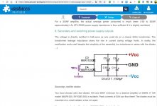
@Drdorkmeister, yes that is very common. The famous "Objective 2 Headphone Amplifier" (sometimes called O2 HPA) does that very thing. It's called Two Half-Wave Rectifiers and it has twice the ripple voltage of a Full Wave Rectifier, for the same amount of filter capacitance. Why? Because the filter capacitor is re-charged twice as often with a FWR as with a HWR.
I used this Two Half-Wave Rectifiers circuit in my Azul headphone amp, and also in my Rojo headphone amp. I exhibited & demonstrated those HPAs at Burning Amp Festival 2019, and listeners seemed to like the sonics.
I also offer this circuit as one of the options in the VRDN power supply PCB that can be freely downloaded from this Forum.
It's a nice option because it allows you to get plus and minus DC supply voltages, from a single wall wart transformer. An AC wall transformer. So the mains voltage never enters the DIY audio equipment cabinet; only the lower voltage AC which is the transformer secondary. The size and weight of the transformer is removed from the chassis. So we can build ultra-slimline line level gear.
Thanks Mark, I just started reading about the IC's that texas instruments makes to do this very thing. Something new every day.
The Texas Instruments TLE2426 “rail splitter” is a neat IC.
It’s intent is to make a virtual ground in the middle of a single DC supply, whereas you can do it natively with a single AC winding... as well as get more voltage (DC) at the output because of the way AC and DC volts are measured. 🙂
It’s intent is to make a virtual ground in the middle of a single DC supply, whereas you can do it natively with a single AC winding... as well as get more voltage (DC) at the output because of the way AC and DC volts are measured. 🙂
Hello all,
I have a curious problem. I've built a power supply using the Universal Power Supply boards, fed through a DIY audio soft start board and an Antek 300VA transformer. Everything is working well; I get 24 volts + and - on the respective rails. Except, on one board the LED isn't working. I checked the resistor - 15k. I then checked the voltage across the LED: 24volts. So, a blown LED. But I'm not sure why I'm getting 24v across it when the resistor is fine and there don't appear to be any connections (bad solders, stray bits of wire) that could be causing a problem? The other rail is fine: 1.6 volts across the LED.
Not a huge problem: I'm getting the voltage I want, the soft start is working fine. I can live without the LED. But I just want to make sure there aren't any hidden fishhooks; that this might be pointing at a bigger problem?
Any help gratefully received!
- Home
- Amplifiers
- Power Supplies
- diyAudio Power Supply Circuit Board v3 illustrated build guide