PhiDAC hex kits with pre-built filters
PhiDAC hex kits with pre-built filters
Load current is 110mA
George
This looks interesting. For a negative cap multiplier would I just replace with opposite polarity transistors?
I've made a test pcb design for smaller current needs. The size is about 47mm x 18mm. I added some jumpers so it could be used with LM337 as well, just that I need to make sure the cap multiplier design is ok for negative as well. The performance should be really good.
Without the LM337 jumpers it could also be diy-ed. I think the separate design for LM337 could be diy-ed as well. But I need to make sure the cap multiplier design is ok for negative as well.
I think the only "special" part is the 1210 220uF cap, all the other parts are dirt cheap. This should be ok for up to 15Vout. There's also space for a small pot but I didn't look too much into that. It could be omitted if not needed.
edit: I also think that once the comp network is found it should work on any board without the need to always adjust it.
You just need need to feed the raw DC into it, so you'd have a transformer - bridge - C or CRC/CLC filter then this supply.
2nd edit: I need to replace that 1210 cap, I can't find it for 16V rating. Only 6.3V. Maybe a tantalum or I increase the size a bit for a 6.3mm smd electrolytic.

Last edited:
A reminder to all participants of this thread (including mods?): this is DIYaudio, and the proposed solutions may have some merit, but they are mainly intended to be fun, and stimulate creativity, and not to meet some productivity criterion (they don't exclude it either)
I think that this main goal has been achieved here.
It also allows people from less favoured regions of the world (70% of the human population?) to access top notch performance with a bit of hardwork, instead of just ordering from Mouser, RS, or whatever, something taken for granted when you live in the EU or the US.
The point is not raw, immediate brutal efficiency, but tweaking, optimizing (and this does not contradict determinism, quite the contrary).
DIYaudio has sections that do not fall into the brutal efficacy category: Tube/Valves and Pass Labs amongst other examples, yet they are cherished by a great number of members.
Morality: if you don't like it, move along; if you have a constructive comment (and it can be negative), post it.
If you don't like something because.. you just don't like it, simply ignore it.
I have an advice for people searching for the ultimate cost/applicabilty/performance tradeoff: look for native Chinese IC's; I don't mean second sources, but real, internal-use Chinese chips.
They aren't generally advertised on the internet, because the internal market of Huawei, etc is sufficiently large to ensure profitability.
They do not perform as well as flagships from AD, etc, but their cost/performance ratio is unbeatable.
Getting the data or the parts themselves could be challenging, but if you are really intent on getting the best deal for a minimal money, they are the way to go.
Parts from AD etc will remain the best absolute performers, at a cost though (for the moment....)
Hi, could you give a hint with regards to the Chinese regulators? A type number, (subjective) performance, data sheet ?
Last edited:
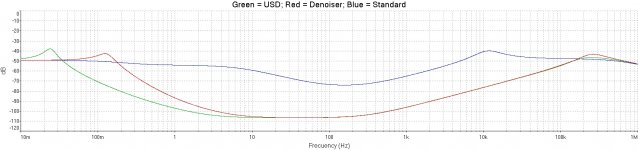
I did some more tests with the simple dienoiser. At first I used a bc327/bc337 pair and I switched to a 330k resistor and 100uF cap. The LM317 result wasn't so promising so I switched to bc550c/bc560c and 220uF. Then I compared to the lm317 denoiser and the result was similar. The overall noise floor was 2-3dB lower for the simple dienoiser but the psrr wasn't as good as the denoiser.
Here's a comparison between the simple dienoiser, denoiser and normal dienoiser. Denoiser is teal, simple dienoiser is yellow and normal dienoiser is red:

Then I replaced the LM317 with LT1084 and it would oscillate (I think) after few minutes. I then added 10nF between C-E of Q1 and seemed to do something but still be unstable, then added another 10nF and that seems to have stabilized it. Now with the LT1084 it's interesting as both the denoiser and simple dienoiser have almost identical result. Denoiser is teal and simple dienoiser is yellow:

So I presume that if LT1084 was stable with just 20nF then you can just add it to most lm317 type regs + simple dienoiser. But the performance seems to be around that of the denoiser for LT1084 and for LM317 it showed a lower PSRR than denoiser. The overall part count is lower for the simple dienoiser vs denoiser but I'd go for the denoiser if I had to choose.
Also looking at the difference between the denoiser and normal dienoiser I don't see that much of a difference (around 10dB). I didn't test Cadj because the denoiser is pretty spot on at around 35dB reduction vs Cadj.
edit: also didn't see a performance difference with LM317 between 220uF and 1000uF cap. Cout was 100uF(200mOhm ESR) for LM317 and 2200uF(50mOhm) for LT1084. Vout was 12V and around 80mA.
Here's a comparison between the simple dienoiser, denoiser and normal dienoiser. Denoiser is teal, simple dienoiser is yellow and normal dienoiser is red:
Then I replaced the LM317 with LT1084 and it would oscillate (I think) after few minutes. I then added 10nF between C-E of Q1 and seemed to do something but still be unstable, then added another 10nF and that seems to have stabilized it. Now with the LT1084 it's interesting as both the denoiser and simple dienoiser have almost identical result. Denoiser is teal and simple dienoiser is yellow:
So I presume that if LT1084 was stable with just 20nF then you can just add it to most lm317 type regs + simple dienoiser. But the performance seems to be around that of the denoiser for LT1084 and for LM317 it showed a lower PSRR than denoiser. The overall part count is lower for the simple dienoiser vs denoiser but I'd go for the denoiser if I had to choose.
Also looking at the difference between the denoiser and normal dienoiser I don't see that much of a difference (around 10dB). I didn't test Cadj because the denoiser is pretty spot on at around 35dB reduction vs Cadj.
edit: also didn't see a performance difference with LM317 between 220uF and 1000uF cap. Cout was 100uF(200mOhm ESR) for LM317 and 2200uF(50mOhm) for LT1084. Vout was 12V and around 80mA.
Last edited:
Hi, could you give a hint with regards to the Chinese regulators? A type number, (subjective) performance, data sheet ?
They are used inside professional equipments from ZTE, Huawei, etc, and probably elsewhere too, but now that I am retired, I do not have access any more to the equipments, and anyway the data was extremely scarce and hard to get.
In fact, there is a whole alternative ecosystem unknown to us, westerners, not only voltage regulators.
With some determination and insider's information, it should be possible to find documentation and purchase a quantity (certainly not a small one though)
Or brute force. A cascade of two Jung/Didden Super Regulators uses more parts, more PCB area, more heat dissipation, more BOM line-items, greater cost, and a lot more In-to-Out voltage drop. On the other hand you can buy all the parts in thru hole packages from Mouser Portugal or Mouser Finland or DigiKey France, and you can also obtain the manufacturer's datasheets very easily. The cascade will give you better Line Rejection (PSRR) and output noise. You can scale up to 3 amps or down to 50 milliamps of output current capability, however you wish. With careful design you'll get lower output impedance too.
I'll try the cap multiplier - lm317 + dienoiser combo for better PSRR. Part count is still small.
I'll try the cap multiplier - lm317 + dienoiser combo for better PSRR. Part count is still small.
If you go this route I suggest you replace the cap multiplier. Looking at George's measurements (or just by simulating) the cap multiplier can be improved. Maybe replace the BC559 stuff with just 2nd order RC filter at the base of the pass transistor.
I'm still playing with the sims, didn't yet decide on the exact circuit. It makes the lm317+denoiser/dienoiser even more of a good option.
I did some more tests with the simple dienoiser. At first I used a bc327/bc337 pair and I switched to a 330k resistor and 100uF cap. The LM317 result wasn't so promising so I switched to bc550c/bc560c and 220uF. Then I compared to the lm317 denoiser and the result was similar. The overall noise floor was 2-3dB lower for the simple dienoiser but the psrr wasn't as good as the denoiser.
Here's a comparison between the simple dienoiser, denoiser and normal dienoiser. Denoiser is teal, simple dienoiser is yellow and normal dienoiser is red:
Then I replaced the LM317 with LT1084 and it would oscillate (I think) after few minutes. I then added 10nF between C-E of Q1 and seemed to do something but still be unstable, then added another 10nF and that seems to have stabilized it. Now with the LT1084 it's interesting as both the denoiser and simple dienoiser have almost identical result. Denoiser is teal and simple dienoiser is yellow:
So I presume that if LT1084 was stable with just 20nF then you can just add it to most lm317 type regs + simple dienoiser. But the performance seems to be around that of the denoiser for LT1084 and for LM317 it showed a lower PSRR than denoiser. The overall part count is lower for the simple dienoiser vs denoiser but I'd go for the denoiser if I had to choose.
Also looking at the difference between the denoiser and normal dienoiser I don't see that much of a difference (around 10dB). I didn't test Cadj because the denoiser is pretty spot on at around 35dB reduction vs Cadj.
edit: also didn't see a performance difference with LM317 between 220uF and 1000uF cap. Cout was 100uF(200mOhm ESR) for LM317 and 2200uF(50mOhm) for LT1084. Vout was 12V and around 80mA.
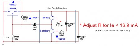
The Ultra Simple Dienoiser allows great flexibility in the choice of R and C, without appreciable detriment to its performance.
A small advantage can be perceived between 2KHz and 20KHz, relative to denoiser, with a simpler and cleaner spectral content.
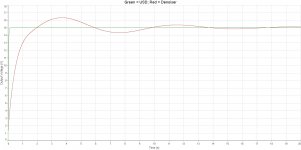
The difference that could show between a lower value of C (100 to 220 uF) and a significantly higher one (like 1000 uF) could be seen in the transient state. A lower value of C yields greater oscillation amplitudes, but in less time. A higher value of C yields lower oscillation amplitudes, but in a longer time.
I didn't see it specified, ¿what value of Cadj. have you used for the Ultra Simple Dienoiser? ¿10 uF or 220 uF?
Have you tested the USD (Ultra Simple Dienoiser) with the dreaded LM337?
Great job, Trileru!!!.
Best regards
Last edited:
I didn't see it specified, ¿what value of Cadj. have you used for the Ultra Simple Dienoiser? ¿10 uF or 220 uF?
Have you tested the USD (Ultra Simple Dienoiser) with the dreaded LM337?
I used 10uF. I didn't test LM337 as I have to switch the polarity of too many parts on the diy supply. I will test it once I gather more things to test LM337 with. But by my guess it should work no issues, especially with the 20nF comp. LM337 needed a low ESR output cap with the normal dienoiser, just like LT1084. Once I used a low ESR output cap I could get them to work with the normal dienoiser, so I figure the LM337 will surely work with the USD.
Complementing the measurements that Trilero kindly carries out, I upload a comparison between a normal LM317 scheme suggested by the manufacturer, the Denoiser and the USD. These last two, operating at a similar collector current (5,785 mA approx.).
As you can see, both the Denoiser and the USD show similar PSRR vs. frequency (in audible range). There could be a slight advantage in favor of the USD of between 3 to 4 dB outside the audible range (265 KHz, according to simulations), although at that frequency it has not been verified yet, it is possible to verify a small difference between 2KHz to 20 KHz in Trileru measurements (giving as probable what the simulation predicts at 265 KHz). In any case, it would be necessary to check under which collector current regime both configurations were operating, since they should be compared at a similar regime.
What is visibly different is the transitory response, a situation that in the Denoiser is not the most favorable. The USD presents a much more immediate response on the first connection.
What must be highlighted in the USD is that a Cadj of only 10 uF could be used, for similar performance to even something more extended in frequency, a value that is more common to find in standard power supplies, than the 220 uF necessary on the Denoiser.
Best regards
Attachments

Last edited:
In the Denoiser, the cause of the not-so-desired transient response is the resistive collector load.
The value of R in the comparison was 760 K approx, to allow a similar value of collector current (both in the Denoiser and in the USD). It is obvious that a standardized value was not sought, but only to make the comparison.
Depending on the output voltage of the regulator, the characteristics of the signal transistors used and the collector current, it will be the corresponding value of R.
To make it fairly universal, a 50K trimpot (up to 6V) could be used instead R; 100K (between 6V and 9V); 200K (between 9V and 12V); 500K (between 12V and 19.5V); 1M (between 19.5V and 28.5V) and 2M (between 28.5V and 37V).
Best regards
You hit the nail on the head: it has to have the very exact value required to keep both transistors in linear mode.It's not clear what value is that resistor between both transistors bases.
Can you specify?
Both behave as CCS's, and tiny differences in Ic will result in one of the transistors being saturated.
If the transistors have a very similar HFe, and a lowish Vaf, they might find an equilibrium, but it will be hairy, and the resistor value will serve as a fine-tune tweaking.
Without feedback, the DC conditions will be very unstable, and the circuit will be unusable in practice.
It's OK to speculate in sim, but I do not recommend using it without further stabilization measures
+1
Unpredictable circuit.
Simulation artifacts only.
A perfect example of what to not do with simulations.
Unpredictable circuit.
Simulation artifacts only.
A perfect example of what to not do with simulations.
You can render the circuit insensitive to beta value(s) by adding two resistors, whoop de do.
- Home
- Amplifiers
- Power Supplies
- D-Noizator: a magic active noise canceller to retrofit & upgrade any 317-based VReg