I’m a new owner of what appears to a be a very well used example of an ex BBC Sp10 mrk2 p/l with its original psu and control box
After a clean of the bearing and a new thrust pad and ball and also a recap on the deck and the psu it worked great on all speeds which was pleasant.
Before the recap pressing start would only start the deck every few goes and sometimes it would start then stop itself really quickly which was somewhat amusing with all the loud clicks from the brake mech. I found the electrolytic cap that serves the stop start section had leaked and a new cap solved this.
I also replaced the start stop switch as this had seen a drinks spillage at some point in its life and wasn’t working so well.
After this I added in a wee led to replace the 140v bulb
I have started to remove the control box following the very helpful and informative post by [mention]Aleks1 [/mention] (posts 999, 1001) but have run into some issues....
The start button was wired to a header on the left of the logic board at cn202 but after doing the mods to convert it I have wired the start switch to the where the rest of the 33/45 buttons which go on the connecting pcb as I seem to get better results with it there.

Currently I can select any of the three speeds but when I press start the platter stays still, it does however actuate the brake solenoid when start / stop is pressed.
If I spin the platter forwards then press start it brakes the platter as if the brake mech is seeing the start/stop command but it doesn’t quite command the motor to go so I would be greatly appreciative if anyone could point me in the right direction ?
I do not have a scope unfortunately and have never used one.
Changes I made
R281 I changed to a 56k resistor.
R166 I also changed to 56k
C203 I added this on the back of the logic board according my to Aleks
0.1uf capacitor (wima type as it’s all I had available ) between start switch and gnd
A jumper between ST and VV


Mods already in place
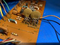
Piggybacked on R233 I have what appears to be a 0.047 mlcc capacitor which is marked on the PL circuit diagram.

I also have a black wire small jumper on the connection pcb which appears to be a connecting two 0v lines coming off the logic pcb (without this jumper my led strobe mod doesn’t work)
See pic below
View attachment 1
Many thanks for this amazing and informative resource collated by everyone here making this a special place !
After a clean of the bearing and a new thrust pad and ball and also a recap on the deck and the psu it worked great on all speeds which was pleasant.
Before the recap pressing start would only start the deck every few goes and sometimes it would start then stop itself really quickly which was somewhat amusing with all the loud clicks from the brake mech. I found the electrolytic cap that serves the stop start section had leaked and a new cap solved this.
I also replaced the start stop switch as this had seen a drinks spillage at some point in its life and wasn’t working so well.
After this I added in a wee led to replace the 140v bulb
I have started to remove the control box following the very helpful and informative post by [mention]Aleks1 [/mention] (posts 999, 1001) but have run into some issues....
The start button was wired to a header on the left of the logic board at cn202 but after doing the mods to convert it I have wired the start switch to the where the rest of the 33/45 buttons which go on the connecting pcb as I seem to get better results with it there.
Currently I can select any of the three speeds but when I press start the platter stays still, it does however actuate the brake solenoid when start / stop is pressed.
If I spin the platter forwards then press start it brakes the platter as if the brake mech is seeing the start/stop command but it doesn’t quite command the motor to go so I would be greatly appreciative if anyone could point me in the right direction ?
I do not have a scope unfortunately and have never used one.
Changes I made
R281 I changed to a 56k resistor.
R166 I also changed to 56k
C203 I added this on the back of the logic board according my to Aleks
0.1uf capacitor (wima type as it’s all I had available ) between start switch and gnd
A jumper between ST and VV
Mods already in place
Piggybacked on R233 I have what appears to be a 0.047 mlcc capacitor which is marked on the PL circuit diagram.
I also have a black wire small jumper on the connection pcb which appears to be a connecting two 0v lines coming off the logic pcb (without this jumper my led strobe mod doesn’t work)
See pic below
View attachment 1
Many thanks for this amazing and informative resource collated by everyone here making this a special place !
Hello "deburgh" (sorry, don't know your name...),
in case you don't have schematics of your SP-10, refer to vinylengine.com to find a bunch of useful material. You will probably find, though, that without some measuring equipment you will have a hard time to repair this precious drive unit or its power supply...
Regards,
Winfried
BTW: Your last attachment in the post leads to an error message...
Hi guys - very weird timing, but I've also just acquired a P/L model and am also interested in the mod to remove the SH-10C.
As with Deburgh, I also don't personally own a scope, although do have access to them at work, and some helpful colleagues who can show me the ropes.
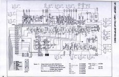
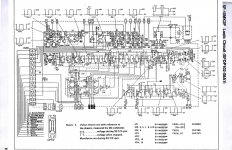
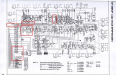
As a starting point, I created the following overlay(s) of the circuit diagrams to highlight the differences between the logic board which was modded earlier in the thread (the RP2/9) and the P/L board.
The only problem is, I'm not adept at deciphering circuits 😕
So, is the same mod feasible with the P/L circuit, or do the highlighted differences on the original boards change the work required?
Any help much appreciated!
As with Deburgh, I also don't personally own a scope, although do have access to them at work, and some helpful colleagues who can show me the ropes.
As a starting point, I created the following overlay(s) of the circuit diagrams to highlight the differences between the logic board which was modded earlier in the thread (the RP2/9) and the P/L board.
The only problem is, I'm not adept at deciphering circuits 😕
So, is the same mod feasible with the P/L circuit, or do the highlighted differences on the original boards change the work required?
Any help much appreciated!
Attachments
Hello "deburgh" (sorry, don't know your name...),
in case you don't have schematics of your SP-10, refer to vinylengine.com to find a bunch of useful material. You will probably find, though, that without some measuring equipment you will have a hard time to repair this precious drive unit or its power supply...
Regards,
Winfried
BTW: Your last attachment in the post leads to an error message...
Thanks Winfried, the last image was the same as the first which is why Its maybe errored
Currently I have both the original and the p/l diagrams from vinyl engine and am looking for some pointers for my issue
Thanks
Chris
Guys sorry to interrupt your conversation, where we buy the thrust cap and new bearing ball now?
Woodsong Audio sells them via their website and also on ebay.
Maybe there are other vendors but this is the one I am aware of. I still need to buy these parts for my SP10...
Maybe there are other vendors but this is the one I am aware of. I still need to buy these parts for my SP10...
SP-10 MK2 P/L PCBs
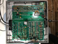
Ok, so I've opened her up and it looks as though the logic board (bottom left) is the same as Alek's board which he successfully modified in post no.999
This P/L variant has the start/stop logic components - which makes sense as the onboard start/stop is functional (with the SH-10C at the moment).
I can't find any images showing the complete PCB setup in Alek's RP2/9, but I would imagine the other boards are the same? If so, the mods should be transferable, but I know that deburgh hasn't quite got them working.
Any help appreciated 🙂
Attachments
Hallo, I received a very messy SH10E power supply and not work because the dual diodes marked on the diagram D403 404 405 406 are not there, consulting the service manual I read the abbreviations that are RVD10DC2 and RVD10DC2R and unfortunately they are obsolete.
I saw that Technics has adopted them on a lot of past productions (deck and turntable).
I thought I'd wait a good moment to retrieve these components from some pcb if I can find them for sale on ebay assuming they are compatible but I can't know for sure, or alternatively I should try to look for compatible modern components to buy new and to easily insert on the pcb in place of the missing ones without forced adaptations but I have no idea what to look for.
Some advice?
Thanks.
Last edited:
@jp many thanks.
Are they oversized for power supply? Did you have to replace or reinforce other components downstream of the fast recovery diodes?
Are they oversized for power supply? Did you have to replace or reinforce other components downstream of the fast recovery diodes?
UF, 1N, won't matter as long as the ratings are at least what the circuit needs. 4007 is a cheap sure bet that I had on-hand.
@JP
well, many thanks; so just I put diodes UN 4007 and I leave everything else unchanged from what i understand. 🙂
well, many thanks; so just I put diodes UN 4007 and I leave everything else unchanged from what i understand. 🙂
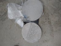
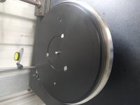
I thought I would post this platter I made for a DIY member for a chassis-less SP10. It's Stainless Steel and Delrin.
First pic is 322x20mm Stainless blank.
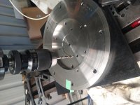
The pins sticking up from the SS in the 3rd pic are for SP10R M5 lifting handles. I don't have scales rated for more than 5kg but estimated weight is about 10kg.
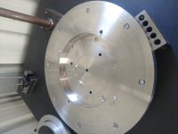
When I installed it on my motor the runout was not so good so I checked the mating surfaces.
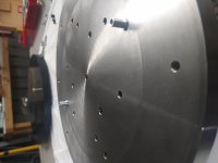
This the platter mating surface
DIY SP10 Stainless Steel platter. - YouTube
All the runout is in the motor.
Technics SP10 motor runout - YouTube
.
First pic is 322x20mm Stainless blank.
The pins sticking up from the SS in the 3rd pic are for SP10R M5 lifting handles. I don't have scales rated for more than 5kg but estimated weight is about 10kg.
When I installed it on my motor the runout was not so good so I checked the mating surfaces.
This the platter mating surface
DIY SP10 Stainless Steel platter. - YouTube
All the runout is in the motor.
Technics SP10 motor runout - YouTube
.
Attachments
Last edited:
Thanks, Don't know how it sounds yet. It will not fit a stock SP10, it was made to order.
I'll be delivering it in a couple of weeks when the NSW - Vic boarder opens. Then I'll have a chance to listen to it back to back with the stock platter
I'll be delivering it in a couple of weeks when the NSW - Vic boarder opens. Then I'll have a chance to listen to it back to back with the stock platter
All the runout is in the motor.
Technics SP10 motor runout - YouTube
mmmmmmm.........need to worry about an imbalance of that entity?
Unbalanced the counterplate or is the pin seat not perfectly vertical in your opinion?
I put the motor spindle with platter mount in the lathe, spun it slowly (20rpm), checked spindle runout to platter mounting face runout. Platter mounting face runout was about 0.05mm TIR (Total Indicated Runout).
After a LOT of measuring and re-measuring I came to the conclusion that the runout seen in the video is caused by the bearing sleeve not being perpendicular to the motor mounting face, the bit that screws to the SP10 chassis.
This may not be an issue as when we level a TT the usual place to put the level is on the platter so this would negate the effect.
Next project is machining myself a SS platter to stock dimensions (the 2nd SS blank) and modifying a motor to increase the bearing spindle size.
This may not be an issue as when we level a TT the usual place to put the level is on the platter so this would negate the effect.
Actually the reasoning is ok. 🙂
- Home
- Source & Line
- Analogue Source
- The Incredible Technics SP-10 Thread