Question: if both inputs (+-) are shortened against gnd (black cable), can I be absolutely certain that the OL-3 board is not interfering? Or should I remove P18, P18, P19 from AC-8.5 to check this?
You have an XLR input, right? Simply connect pins 2 and 3 to pin 1, that’s the proper way.
The OL3 board can only interfere when something is broken on this board, which will become visible as an offset voltage at the LS output.
What exactly is the DC at the LS output from the amp.
But it’s relatively easy to test interference from the OL3 board.
Disconnect the 5 pin connecter from this board and remove it’s red power line from the blue cap.
Hans
Shortening those two resistors to gnd would really be a bad idea, never try to do that.If no result, I might have to take apart the boards and see if I can track the noise backwards from P6, P7. E.g., shortening lines R23, R36 to ground to see what it does.
BR
Hans
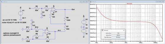
Because I just guessed the noise production yesterday, I wanted to be more accurate and made a model in LTSpice.
The 27.5 BW spec overall is 122Khz including the input filters. To get that, both amps in the circuit diagram below where given a GBW of 5Mhz and the 2.5nV/rtHz noise from a dual LM394.
Overall noise referred to input was now a bit below 8nV/rtHz, times 22 for the gain is 176nV/rtHz.
For a BW of 122Khz this would mean 61uVolt noise at the output.
In the picture below I measured 75uV for a BW of 300Khz, say roughly 0.1mV.
I suspect this 0.1mV is way below the noise of your scope, so what you measure is probably mostly noise from the scope.
Just to verify connect the gnd lead of your probe to the probe itself and see what noise is shown on the screen.
What does your Scope manufacturer specify for the input noise ?
To get a better idea of what's coming out of your amp you should either have a spectrum analyser or a low noise amplifier between the LS output and your scope to isolate the amp's noise from your scope's noise.
For the purpose of a low noise amplifier in between, you could very well use the other 27.5.
Hans.
Attachments
Last edited:
Pretty sure 0.1mV is below scope internal noise, for the Rigol DS1054Z there is no explicit noise specification. Smallest Divider is 1mV. There is a couple-to-gnd function, but I don't know how it's implemented and if it would really show the internal noise only.
Will do the test you described instead, and then measure LS Out with a gnd spring again, that's the most accurate which I can think of. This entry level scope is quite popular, and there tons of noise discussion which I haven't read fully, but the gist seems to be that this thick noisy lines are what you get at the mV level if you have even the shortest antenna to pick up ambient, plus internal noise of course.
The scope has a build-in FFT, I have to try it out.
Thanks for the sim, haven't digested it yet.
Last edited:
To get a more accurate measurement of P11, I will try to measure it directly on AC-8.5. I will have to unscrew the amp channel with heat sink so I get more space.
BR
BR
Last edited:
Did you read the suggestion of putting a second 27.5 in between to amplify the noise a factor 22 ?
But I’m also very interested in the FFT results of your scope.
Hans
But I’m also very interested in the FFT results of your scope.
Hans
second 27.5 in between to amplify the noise a factor 22 ?
Yes, I will get back to that. Must make sure no additional noise is added to output of 1. 27.5.
I also want to scrutinize a bit the noise seen in the previous measurements first.
BR
Last edited:
It will take me some time, but here is a quick'n'dirty FFT of the noise of the 'noisy' 27.5, measured with a smartphone app next to tweeter. Window blackman-harris.
You can spot the switch LS on / off.
If I interpret this correctly, the noise that I hear is 3-5kHz (not just a non-linearity of the phone mic).
left channel x log

right channel x log

left channel x linear

right channel x linear

You can spot the switch LS on / off.
If I interpret this correctly, the noise that I hear is 3-5kHz (not just a non-linearity of the phone mic).
left channel x log
right channel x log
left channel x linear
right channel x linear
Last edited:
Better scope pics coming tomorrow. Just tried with a gnd spring and that makes all the difference. That 5cm gnd crocodile lead is just too long.
Input noise of the scope seems to be <2mV (scope gnd to probe).
Getting LS Out readings from working 27.5 close to that.
BR
Input noise of the scope seems to be <2mV (scope gnd to probe).
Getting LS Out readings from working 27.5 close to that.
BR
When the heatsink is not tightly electrically connected to the chassis gnd...
There's 10 Ohm from the heatsinks to alu strip, so this seems ok.
I spend some time repeating my past measurements. I'm confident the input noise of the scope is <2mV. But even with gnd spring on probe I seem to get EMF, which switches on / off (refridgerator in apartment above?). Perhaps I can move the set-up to a different location, maybe later. If I use 2nd ML as noise amp, I probably will amplify the EMF as well.
Here's a picture of a 'probe to probe-gnd' test.

Then there's the working ML LS Out under optimal conditions for comparison (no EMF at the moment?)

Here's a picture of a 'probe to probe-gnd' test.
Then there's the working ML LS Out under optimal conditions for comparison (no EMF at the moment?)
My point is that even with EMF, the two ML can be compared with respect to LS Out, because the added noise level should be about the same at a given time (I measured repeatedly). Speaker cable makes no difference.
Here is the working ML:
And here the noisy ML:
There is a difference, right?
The new FFT graph (blue line) is jumping around, it does not tell me anything. Either the noise is a mix of all frequencies (other than I thought), or I am operating it not right.
Here is the working ML:
An externally hosted image should be here but it was not working when we last tested it.
An externally hosted image should be here but it was not working when we last tested it.
And here the noisy ML:
An externally hosted image should be here but it was not working when we last tested it.
An externally hosted image should be here but it was not working when we last tested it.
There is a difference, right?
The new FFT graph (blue line) is jumping around, it does not tell me anything. Either the noise is a mix of all frequencies (other than I thought), or I am operating it not right.
So, I'm scratching my head what the source of this heightened LS Out noise of the noisy ML is.
I have compared charge cycles for both 47mF and 1900uF for both ML and they seem ok.
As I wrote before, I temp. changed C21 to a 470uF cap I had and believed the noise got less in this channel.
Let's compare VReg +- for both channels working ML vs. noisy ML.
1. working ML - smooth Vregs


Looks good to me.
I have compared charge cycles for both 47mF and 1900uF for both ML and they seem ok.
As I wrote before, I temp. changed C21 to a 470uF cap I had and believed the noise got less in this channel.
Let's compare VReg +- for both channels working ML vs. noisy ML.
1. working ML - smooth Vregs
Looks good to me.
Now all VRegs for the noisy ML.


Terrible.
Something tells me that must have something to do with the situation at LS Out.
Mind you, I have done the measurements multiple times, making sure difference of the amps does not depenend on EMF.
PS: the 2nd graph is the VReg+ where I put in the temp 470uF. But it was the same (very high) level with the 680uF Sprague as well, I checked! So no change!
What else in voltage regulation could cause this?
Hans, I think the FFT from the scope does not help. Do you still want the .wav from LS Out? Could borrow a USB sound card from friend to record this.
BR
BR
Eventually I follow your suggestion, Hans, and used working ML as amplifier for the LS Out noise of 'noisy' ML.
So, about 150mVpp noise after 22x gain.
I used left LS, which had 14mVpp, so it's not the 22x gain, or about half of the 14mVpp is noise added by scope / probe connector.
The FFT readings I interpret as broadband noise, no specific oscillation (?)
1kHz / 10Khz


So, about 150mVpp noise after 22x gain.
I used left LS, which had 14mVpp, so it's not the 22x gain, or about half of the 14mVpp is noise added by scope / probe connector.
The FFT readings I interpret as broadband noise, no specific oscillation (?)
1kHz / 10Khz
Last edited:
Shortening those two resistors to gnd would really be a bad idea, never try to do that.
I thought R23 R36 are the drive lines, and by using a C to drain AC current to ground I could check if the the noise is there before or after this section.
BR
This is great with the added FFT.
But the BW in the last images is only 500Hz/div so your image covers only 5Khz.
We should try to get the FFT at least at 10Khz/div, that will cover most of the range of your 27.5.
I'll have a look at the manual of your DS1054Z to understand your images.
The good news looking at the FFT's so far is that there seems nothing wrong with your amplifier.
But what seems not OK is the regulated power supply, but the PSRR (power supply rejection ratio) of your amp reduces this to almost invisible levels in the LS output.
I will study those supply images in more detail and come back to you on that, but let's first get the FFT right, this is a fantastic powerful tool when used correctly.
Hans
O.K. I had a look at the manual.
What a lot of functions for such an affordable price !
According to the manual you can set the Hor. scale of the FFT with "Scale and arrow up".
So when you could choose 10kHz/div that would be fine.
When you can't get as high as 10Khz/div you might have to change the timebase from 1msec/div to 100us/div or even 10usec/div/
The vertical scale is ok with 10 or 20dB/div, but it would also be nice if possible to see where 0dBV starts.
Hans
Great, thanks!
Here's the link to the manual in case you don't have it yet: https://www.batronix.com/pdf/Rigol/UserGuide/DS1000Z_UserGuide_EN.pdf
p. 6-47
Tell me the parameters for FFT, I will set it up.
BR
Here's the link to the manual in case you don't have it yet: https://www.batronix.com/pdf/Rigol/UserGuide/DS1000Z_UserGuide_EN.pdf
p. 6-47
Tell me the parameters for FFT, I will set it up.
BR
- Home
- Amplifiers
- Solid State
- Mark Levinson No.27 amplifier,,,NEED HELP