Cooledit and Audition usually normalize to 32768 even when the files are floating point. If they are floating point it does not matter.
Hans,
I'm a little behind, and still trying to understand what you did, and how to include it on my simulation. I'm still here:
FET vs BJT input phono preamp
Already included Paul's model for V15III at the input. Next I will include your anti-RIAA.
One thing I do not understand is AC 8.15.
Is there an asc file for that sim?
From what I get to understand you are trying to simulate the cartridge as much as possible, and I lost myself on what is the preamp schematic and the sim.
These three options I fail completely to understand:
FET vs BJT input phono preamp
I seem to understand the problem now switched to how to better deal with LP clicks and pops, right? And again I don't know what belongs in the schematic and what in the simulation.
Can you help me?
Carlmart, you should really invest more time in reading the posts and somewhat in improving your LTSpice skills.
It was not Paul's model for the V15III, but Marcel's and I already showed it in posting #308.
The AC 8.15 is simply the AC voltage generated by the voltage source.
When you do a right click on a voltage source you can select the waveforms you want in the .tran mode and the voltage amplitude in the AC mode.
But with all your LTSpice questions you can go here:
Installing and using LTspice IV (now including LTXVII). From beginner to advanced.
In the posting with the three simulations I replaced the LT1792 amps by Voltage Dependant Voltage Sources, but instead of telling the gain with one of more digits, I entered a Laplace instruction, replacing all the filters in your sim by simply entering the poles and the zeros.
So what you see is exactly your schematic but with ideal amps and ideal filters.
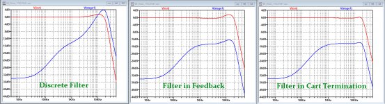
To make it more understandable, I have made three frequency plots of your amp, with the V15III model, including the Cart's mechanical resonance, but now with all your LT1792amps and real components.
The image shows resp the FR at the output of the first stage in blue and your output O in red.
The three plots are showing resp. the FR for the passive filter version that you favoured, a version with the filter function in the feedback loop of the first stage and finally the version with a 4K78 Cart termination replacing the capacitor altogether.
It's quite obvious that the first stage has a ca. 14dB higher amplitude to cope with than in the two other two versions, even higher as the output stage.
That's why I think that the passive 75usec filter may not be the best choice, depending on the amplitude of the pops and clicks for which I have no information.
Hans
It was not Paul's model for the V15III, but Marcel's and I already showed it in posting #308.
The AC 8.15 is simply the AC voltage generated by the voltage source.
When you do a right click on a voltage source you can select the waveforms you want in the .tran mode and the voltage amplitude in the AC mode.
But with all your LTSpice questions you can go here:
Installing and using LTspice IV (now including LTXVII). From beginner to advanced.
In the posting with the three simulations I replaced the LT1792 amps by Voltage Dependant Voltage Sources, but instead of telling the gain with one of more digits, I entered a Laplace instruction, replacing all the filters in your sim by simply entering the poles and the zeros.
So what you see is exactly your schematic but with ideal amps and ideal filters.
To make it more understandable, I have made three frequency plots of your amp, with the V15III model, including the Cart's mechanical resonance, but now with all your LT1792amps and real components.
The image shows resp the FR at the output of the first stage in blue and your output O in red.
The three plots are showing resp. the FR for the passive filter version that you favoured, a version with the filter function in the feedback loop of the first stage and finally the version with a 4K78 Cart termination replacing the capacitor altogether.
It's quite obvious that the first stage has a ca. 14dB higher amplitude to cope with than in the two other two versions, even higher as the output stage.
That's why I think that the passive 75usec filter may not be the best choice, depending on the amplitude of the pops and clicks for which I have no information.
Hans
Attachments
There are several alternative implementations of the RIAA curve discussed here and it is not always obvious to me which topology is under discussion, the passive all-in-one (Muffsy), passive LP-active HP (Borbely) or the "cartridge loaded frequency shaping" as advocated by some forum members.
Hans, is the "discrete filter" simulation you refer to in the previous post using the passive all-in-one? The all-in-one generate the Riaa response by "burning off" about 20dB above 500Hz. Therefore, it typically has more gain in the first stage compared to splitt RIAA networks.
I would be every interested to see the clipping behavior of e.g. the JC using the passive/active topology.
Unfortunately I have no experience in the use of circuit simulation tools.
It would be highly appreciated if someone would take the trouble of simulating this circuit using the same LT1792 for comparison.
Thanks
Lars
Attachments
Last edited:
Hi Lars,
On discussion here is obviously the "Borbely" LP version and not the complete passive Riaa network Muffsy version.
What can be said about clipping is that when using a complete passive network, the second stage has to produce 20dB more gain, which should not be a real problem, so the output amplitude of the first and the second stage are still comparable to the LP version as discussed here and so is sensitivity for clipping.
The point however is that one should carefully keep an eye on the noise directly after the fully passive Riaa network to prevent the RTI (referred to input) noise from too much worsening the noise from the first stage alone.
As long as that's not the case and you are still on the right side of the targeted S/N, there's nothing against it and the FR is probably more correct as in an active setup.
Giving the first stage more gain, makes this stage more sensitive to clipping which should be prevented.
Even for an MC amp is it possible with great care to use complete passive networks as shown in Linear Audio Vol. 12 without affecting the 1.2nV/rtHz RTI noise from the first stage.
Hans
Carlmart, you should really invest more time in reading the posts and somewhat in improving your LTSpice skills.
It was not Paul's model for the V15III, but Marcel's and I already showed it in posting #308.
Of course I did read the posts, only I wasn't understanding what was being done.
I think I did mention Marcel's name a lot, and talked to him, to see I just mixed up the name. But I do know it was Marcel's model you were using.
About my LTSpoice skills are certainly limited, but that's why I was asking for help. If you should have uploaded the asc file you used, as I did, that questions wouldn't have existed.
I do know how to set the .tran mode data, but once again it should have been on the asc file
The three simulations weren't too clear either, and once again uploading the asc file would have been useful.
Things got more and more complicated to understand what you were doing. Sorry not know as much as you do, but uploading the asc files, when available, would have helped me a lot.
To me nothing is obvious yet, and it would be great to know what and why. After all it was me who suggested using Borbely's filter for this project.
You want to learn things, right ?
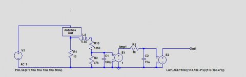
Just copying .asc files without understanding what they do is not helping you.
Try to make in LTSpice the simple schematic in the image below, that will really help you to understand things.
And as a matter of fact the .tran command was in the original image, just look again.
I'm looking forward to see how you succeeded in getting this thing working.
Hans
Attachments
Is this some sort of test?
Do you think I have been simulating all sort of circuits, created by me "just copying .asc files"?
The only thing I'm not experienced with is with Laplace transforms used to simulate cartridge load, so I just copy the device as the designers that do know them use them.
It still does not explain why you didn't load the .asc fles for you what you were simulating.
Given some of your questions it's hard not to come to that conclusion. But Hans is a great teacher. Learn from him.
Now i wonder how is this discussion going to emphasize the differences or simillarities between bipolar and j-fet input phono preamps.Maybe some moderator should cut this discussion on cartridges and variable types of riaa and make it a different topic...
You should probably choose the posts on cartridge simulations and types of riaa networks for best linearity and form a different topic of your own.A moderator can help you with this.Is this some sort of test?
Do you think I have been simulating all sort of circuits, created by me "just copying .asc files"?
The only thing I'm not experienced with is with Laplace transforms used to simulate cartridge load, so I just copy the device as the designers that do know them use them.
It still does not explain why you didn't load the .asc fles for you what you were simulating.
As i understood from Billshurv, Hans has such a topic on carts ...maybe this discussion on carts simulation should be moved into one of Hans topics...
Or you understand that you don't own this thread rather than whining like a kid who dropped their ice cream?
The title of this topic owns it and if its expired i can accept that, but hijacking a topic and chnging its Theme is still an infraction on Diyaudio.I'd say i was really polite to both Carlmart and Hans suggesting that theymight wanna own their own topic .
Cartridge simulations is not the thematic of this Topic.
Here was a request:
Here there was a consent:
There was nothing about simulating cartridges until i put a first model of Shure v15typeIII at Carlmarts request
https://www.diyaudio.com/forums/ana...vs-bjt-input-phono-preamp-15.html#post6359558
But MarcelVDG came with an enhanced model and maybe form that point on the topic should have split:
https://www.diyaudio.com/forums/ana...vs-bjt-input-phono-preamp-28.html#post6365292
which model was improved a bit by Hans
https://www.diyaudio.com/forums/ana...vs-bjt-input-phono-preamp-30.html#post6365814
I can understand that you like thousands pages of diluted topics like Black Hole and John Curl Blowtorch...but here's not the Lounge section.
Cartridge simulations is not the thematic of this Topic.
Here was a request:
https://www.diyaudio.com/forums/ana...vs-bjt-input-phono-preamp-13.html#post6357818OK, I was thinking of opening a new thread for RIAA preamps, discrete and IC, and perhaps it might be more useful to hijack this thread, if you allow me.
Here there was a consent:
https://www.diyaudio.com/forums/ana...vs-bjt-input-phono-preamp-13.html#post6358005do whatever you want as long as it is about comparing fet input with bipolar input preamps...lm4562 is bjt input, ad745 is bi-fet input...As far as i know ad743 and 745 were the lowest noise op-amps just very epensive...
There was nothing about simulating cartridges until i put a first model of Shure v15typeIII at Carlmarts request
https://www.diyaudio.com/forums/ana...vs-bjt-input-phono-preamp-15.html#post6359558
But MarcelVDG came with an enhanced model and maybe form that point on the topic should have split:
https://www.diyaudio.com/forums/ana...vs-bjt-input-phono-preamp-28.html#post6365292
which model was improved a bit by Hans
https://www.diyaudio.com/forums/ana...vs-bjt-input-phono-preamp-30.html#post6365814
I can understand that you like thousands pages of diluted topics like Black Hole and John Curl Blowtorch...but here's not the Lounge section.
Last edited:
My only complaint was that I would have appreciated that the .asc files of what was being done here should have been uploaded, as I did when I first showed several RIAA schematics. I don't think I asked for something unusual.
Try talk to a moderator to make a separate topic on cartridge and riaa network simulations with a proper name and perhaps gather a larger audience and more help. My topic thematic was only about the differences between bjt and fet input preamps and i think that your subject is much more complex and specialized than that. Just don't take it as an offecnce, but i simply hate topics that start with one thing and finish with very different things having hundreds of pages and being very hard to follow.
Is this your topic?
mechanical resonance in MMs
I chequed the last 10 pages of the 168 pages of your topic and there was almost nothing on mechanical resonances there...Is that the trend you like on diyaudio? Assuming that at least 10 pages should have been on topic , 158 pages of nothing about the topic's name isn't really good, don't you agree?
Why don't you ask the pages on mechanical resonances of the shure v15typeiii from this topic to be moved in your topic? I'd fully agree on that. That would make your topic ..more on topic 🙂
Are you here for anything else but quarrel?
Last edited:
- Status
- Not open for further replies.
- Home
- Source & Line
- Analogue Source
- FET vs BJT input phono preamp