A RIAA amplifier with op-amps is simple enough to build on perfboard, but modifying this kit will also work. Do what you like most. R10 and R11 are a bit high if you want low noise, but you can modify them of course.
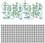
Yes, you're probably right in trying a perf board, also adding the regulation on same board. Something like this would do:
3pcs 8x12cm Double Side Copper Prototype PCB 8*12cm Universal Printed Circuit Board Fiberglass Plate For Arduino Soldering Board|Single-Sided PCB| - AliExpress
For the prototypes, what I do is load a perf board on the pcb program, and then proceed as if I'm drawing a normal pcb.
R10 and R11 on what schematic are a bit high?
No, the Chinese kit was just a means to an end.
The only ones in question are the ones I call LT1792 preamp and Muffsy PP4, also with LT1792.
Do you agree on my comments on the OPA1652? I'm not sure I could use two dual OPAs for both stages on each side. I don't have a model for the OPA1652 I can use.
The only ones in question are the ones I call LT1792 preamp and Muffsy PP4, also with LT1792.
Do you agree on my comments on the OPA1652? I'm not sure I could use two dual OPAs for both stages on each side. I don't have a model for the OPA1652 I can use.
i checked using my settings...indeed, the hybrid passive-active preamp is worse .Lower input saturation, higher distortions...even with +-18v supply. Better go with this but use +-18v , simple 7815/7915 regulators.No need for fancy reg: https://www.diyaudio.com/forums/ana...vs-bjt-input-phono-preamp-15.html#post6360137
Last edited:
Do you agree on my comments on the OPA1652? I'm not sure I could use two dual OPAs for both stages on each side. I don't have a model for the OPA1652 I can use.
I agree with the statement that it doesn't come in a DIP8 package and doesn't fit in the Chinese PCB. I expect you could use it for both stages, and the noise specs are very good for moving magnet.
It would be a good reason to try a prototype board with it.
Rod Elliott's MM preamp uses two dual 5532, but go find a pcb without the parts. I think they sell it as a complete kit too.
But it might be a good reason to simulate Rod's circuit too.
I'm not sure you guessed my approach by now. I do believe in properly assembled parts, particularly when low noise is involved. PCBs are not an easy problem to solve, and through hole passive parts can be easily moved, added or eliminated. As long as you have the basics solved (two single or dual ICs) the rest comes easy.
But I disagree a bit with Dreamth attitude (to call it somehow) towards regulators, and my experience with regulators seems to differ from his. So that's something I will deal my way on whatever pcb approach I pick.
Very interesting his comments on the hybrid passive-active sim, which I thought would be different. That suggests I should pick the passive design as the first to try.
I have been carrying out LTSPice simulations with several power supplies, and the proto pcbs might be a way to start. I enclosed an example on how I have been thinking of dealing with pcb prototypes using proto pcbs.
In that case it was a small add-on circuit for regulators, called the Dienoiser, dealt with on another thread of the forum. But I'm already designing a Jung/Didden pcb with the same approach, and how I would do other prototypes.
Attachments
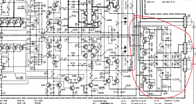
if you really want a very good regulator you can try this modified version of the Technics regulator:
https://www.diyaudio.com/forums/power-supplies/359652-fine-ic-voltage-regulators-28.html#post6353344
the zenner diodes values can get you the wanted output voltage.
or the nakamichi kind of regulators:
https://www.diyaudio.com/forums/power-supplies/359652-fine-ic-voltage-regulators-25.html#post6348364
or the kenwood like type of regulators
https://www.diyaudio.com/forums/power-supplies/359652-fine-ic-voltage-regulators-18.html#post6336611
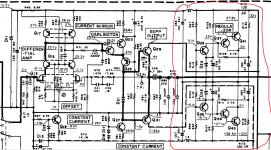
or the additional kenwood regs in the photo below.
Other than that i can tell you for sure that you don't need a damn regulator if you really know how to work the ground plane ! Most commercial products are using regulators because they need to provide a safe voltage supply and a lot of clean current for tons of other circuits than just the phono spread on a big pcb .The lousiest op-amp cand provide 90db PSRR and CMRR where the ear is most sensitive to noise and a simple first order rc filter can eliminate the rest of the HF noise .
BUT, if you don't believe me it's all right...
https://www.diyaudio.com/forums/power-supplies/359652-fine-ic-voltage-regulators-28.html#post6353344
the zenner diodes values can get you the wanted output voltage.
or the nakamichi kind of regulators:
https://www.diyaudio.com/forums/power-supplies/359652-fine-ic-voltage-regulators-25.html#post6348364
or the kenwood like type of regulators
https://www.diyaudio.com/forums/power-supplies/359652-fine-ic-voltage-regulators-18.html#post6336611
or the additional kenwood regs in the photo below.
Other than that i can tell you for sure that you don't need a damn regulator if you really know how to work the ground plane ! Most commercial products are using regulators because they need to provide a safe voltage supply and a lot of clean current for tons of other circuits than just the phono spread on a big pcb .The lousiest op-amp cand provide 90db PSRR and CMRR where the ear is most sensitive to noise and a simple first order rc filter can eliminate the rest of the HF noise .
BUT, if you don't believe me it's all right...
Attachments
Other than that i can tell you for sure that you don't need a damn regulator if you really know how to work the ground plane ! Most commercial products are using regulators because they need to provide a safe voltage supply and a lot of clean current for tons of other circuits than just the phono spread on a big pcb .The lousiest op-amp cand provide 90db PSRR and CMRR where the ear is most sensitive to noise and a simple first order rc filter can eliminate the rest of the HF noise .
BUT, if you don't believe me it's all right...
About a ground plane not being necessary at all, it's not me that don't believe it's necessary: it's Jan Didden, the guy who designed the first pcb for the Jung Super Regulator. It did have a ground plane on that version.
But on the current Super Regulator thread here, quite a long one, he said that a ground plane was not necessary and it was eliminated.
The pcb boards they sell now at the DIYaudio shop are two-sided, but with no ground planes. What it does have is a proper handling of the separate grounds just joining at one point.
Today I was playing with LTSpice in a different direction, or not quite so.
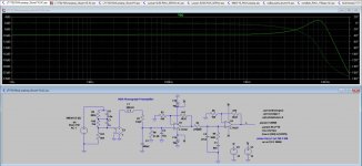
What I did was take Rod Elliott's original RIAA preamp, published on his site, which he designed for using two stages of an NE5532. I never listened to the original design, so I can't say anything about, pro or con.
Hi-Fi RIAA Phono Preamp
The fun thing about LTSpice is that you seem to be able to play with anything, and even get good results. But you can't know if it really means a real life project or just a "soap bubble".
Though I was not interested in the 5532, particularly because of the feedback DC blocking you need with it, what I was interested is its architecture. It also combines active with passive eq, which I did mention Erno Borbely had said was the best of both worlds.
So what I did was load the schematic into LTSpice, but using the same LT1792/LT1037 of the other preamp.
Now: Borbely's proposal was to use first the passive stage and then active one after it. So I inverted the stages on Elliott's preamp. With an accidental mistake: now the first stage was the LT1037 and the second stage the LT1792.
The resulting THD on the simulation was the lowest of them all. But Marcel vdG had been very picky on using a BJT as first stage for a moving magnet. I'm not sure how Marcel qualifies the LT1037.
The second thing I also perceived is that the LT1037 is a VERY expensive chip, which is not something I really want. There might be other more affordable singles that are good replacements for it, which I don't know.
So I put the chips in the "original" order: LT1792 first, LT1037 second. The THD was also good, but not as much as the other.
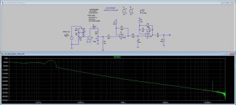
Then I replaced the expensive LT1037 for another LT1792, and ran it.
THD was very good (I think) and THD curve looks quite clean.
If you can please check on these results, and tell me if what I got is real or just a "soap bubble".
What I did was take Rod Elliott's original RIAA preamp, published on his site, which he designed for using two stages of an NE5532. I never listened to the original design, so I can't say anything about, pro or con.
Hi-Fi RIAA Phono Preamp
The fun thing about LTSpice is that you seem to be able to play with anything, and even get good results. But you can't know if it really means a real life project or just a "soap bubble".
Though I was not interested in the 5532, particularly because of the feedback DC blocking you need with it, what I was interested is its architecture. It also combines active with passive eq, which I did mention Erno Borbely had said was the best of both worlds.
So what I did was load the schematic into LTSpice, but using the same LT1792/LT1037 of the other preamp.
Now: Borbely's proposal was to use first the passive stage and then active one after it. So I inverted the stages on Elliott's preamp. With an accidental mistake: now the first stage was the LT1037 and the second stage the LT1792.
The resulting THD on the simulation was the lowest of them all. But Marcel vdG had been very picky on using a BJT as first stage for a moving magnet. I'm not sure how Marcel qualifies the LT1037.
The second thing I also perceived is that the LT1037 is a VERY expensive chip, which is not something I really want. There might be other more affordable singles that are good replacements for it, which I don't know.
So I put the chips in the "original" order: LT1792 first, LT1037 second. The THD was also good, but not as much as the other.
Then I replaced the expensive LT1037 for another LT1792, and ran it.
THD was very good (I think) and THD curve looks quite clean.
If you can please check on these results, and tell me if what I got is real or just a "soap bubble".
Attachments
20khz is irelevant for measurements 1khz,5khz and 8.4khz(the resonance point ) at 250...350mv input(15v for 300mv input before antiriaa filter in your case) are the important one.71.5 signal to noise ratio at 1khz...
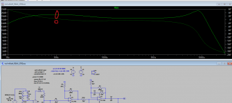
Now the frequency plot at low frequencies doesn't look ok.
Now the frequency plot at low frequencies doesn't look ok.
Attachments
Last edited:
Why is that every simulation you put V- is reversed?
Where?
Sorry, I didn't run any other simulations yet, like FR or noise. Was just starting.
Thanks about the frequency tips. I will check on them.
How do you compute the S/R to get to 71.5 @ 1K?
What can be affecting the low response?
Oh, I think saw what you mean with the reversed V-.
Try to reverse the symbol and see what happens.
Try to reverse the symbol and see what happens.
All,
Marketing/systems guy from TI here - I didn't read through all of the threads here, but have you tried OPA1656? Exceptionally low noise for a FET input device. I put a RIAA circuit in the data sheet, see page 19.
Marketing/systems guy from TI here - I didn't read through all of the threads here, but have you tried OPA1656? Exceptionally low noise for a FET input device. I put a RIAA circuit in the data sheet, see page 19.
i already reversed that 🙂 i have no idea how to modify those filters...I can only place a 120...150nf capacitor at the input and you get a subsonic and anti rumbble filter as well
If I reverse them on my plots I do not get V-. I can't explain why.
Now, to start with, I don't get that low response you get on my simulation on the Rod Elliott preamp version.
I run the other LT1792 preamp with the V15 load, passive filter, and the FR response is flatter than the Rod Elliott version
Now, to start with, I don't get that low response you get on my simulation on the Rod Elliott preamp version.
I run the other LT1792 preamp with the V15 load, passive filter, and the FR response is flatter than the Rod Elliott version
Attachments

- Status
- Not open for further replies.
- Home
- Source & Line
- Analogue Source
- FET vs BJT input phono preamp