Attachments

Last edited:
Because of their huge equivalent input noise current, especially the LT1028. It's a different matter for moving coil, of course.
As far as input noise current goes, J.Curl claimed that the Ortofon Black was one of the highest inductance of the modern MM pickups in a thread a couple of years back when someone complained about input noise on the JC3-jr RIAA.
According to Ortofon web-page it's got a sensitivity of 5mV with impedance of 1200-ohm/630mH, so higher than the 1350-ohm/500mH proposed by Dremth for simulating Shure v15typeIII.
The Rega Exact has a claimed sensitivity approx. 2-3 dB higher at 7mV and according to postings on the Graham Slee forum has a lower resistance at 166 ohm, with inductance of 100mH.
As such If so I guess this can be considered "worst case" for high current noise inputs. and probably best served by discrete J-FET input amplifiers or AD743 / AD745 Op-Amps.
A different type of pickups that is used with the MM input of the RIAA is the high Output MC type. I have not to been able to find inductance numbers these but resistance seem to by much lower, between 40-100 ohm.
I suspect they will be in the opposite end of the scale and less affected by the current noise.
Last edited:
I think your inductances are off by a factor of 1000, a Shure V15 III has an inductance of about 460 mH...500 mH, not uH.
Wooops.
Thanks' for pointing out the error, I have corrected my previous post.
From a noise perspective, I guess this makes the Rega less sensitive to current noise than what I originally assumed with its claimed higher output and lower impedance compared to the the Ortofon and Shure.
BTW: The 166ohm/100mH numbers claimed on the graham Slee forum is not to far off from the numbers a got by attaching RLC meter to a dead "gray" Exact model of the first generation. I got a meter reading of 100 ohm/100 mH.
Last edited:
A practical project for implementing a circuit like the LT1792 I proposed.
Why not take an existing being sold as preamp kit and assemble it with the parts we want, perhaps even using some of the kit parts, like bypassing caps?
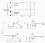
Looking around I found this RIAA kit that has an architecture quite similar to the LT1792 based preamp, with different passive parts.
ZEROZONE MMCF10 Hifi LP Phonograph MM Amplifier Kit / RIAA Phono Preamplifier Kit DIY|preamplifier kit diy|phono preamplifier kitpreamplifier kits - AliExpress
It's sold by other vendors, including eBay. You can also get the bare pcb.
MMCF10 HIFI LP phonograph MM amplifier RIAA Phono preamplifier PCB Free ship|Amplifier| - AliExpress
I have found this way of assembling preamps and power amps a good way to get things done, not getting involved with pcb home fabrication. If you buy the kit, which is not too expensive, you get other stuff you could use.
Before advancing on this, I would like your opinion on this approach to build a RIAA preamp. Why yes, why not, how to handle it.
Why not take an existing being sold as preamp kit and assemble it with the parts we want, perhaps even using some of the kit parts, like bypassing caps?
Looking around I found this RIAA kit that has an architecture quite similar to the LT1792 based preamp, with different passive parts.
ZEROZONE MMCF10 Hifi LP Phonograph MM Amplifier Kit / RIAA Phono Preamplifier Kit DIY|preamplifier kit diy|phono preamplifier kitpreamplifier kits - AliExpress
It's sold by other vendors, including eBay. You can also get the bare pcb.
MMCF10 HIFI LP phonograph MM amplifier RIAA Phono preamplifier PCB Free ship|Amplifier| - AliExpress
I have found this way of assembling preamps and power amps a good way to get things done, not getting involved with pcb home fabrication. If you buy the kit, which is not too expensive, you get other stuff you could use.
Before advancing on this, I would like your opinion on this approach to build a RIAA preamp. Why yes, why not, how to handle it.
Attachments
there's no real reason to use lm7815 after 7818 with a phono preamp.The op-amps PSRR is so high that you don't actually need any regulation at all.18v supply is much better for phono riaa than 15v in your case.The only reason to use a regulator in your schematic is to make sure the op-amps rail supplies won't exceed the max supply of your op-amps.
Last edited:
This is just the beginning of my proposal. Several changes would have to be implemented.
If you agree on the principle for this project, I would go forward and propose the changes that should be made.
Of course I would never use a fixed regulator like the one they used, certainly not two regulators in series. The minimum I would do is put two LM317/337 small regulators you find on eBay, which should be considerable advance on what they used.
''The minimum I would do is put two LM317/337 small regulators you find on eBay, which should be considerable advance on what they used.''
not really...78xx series is a bit noisier, but it's definitely faster and takes less space...I wouldn't loose my time with assesing which regulator is better...I used more advanced regulators because my phono preamps also involves external transistors and i also supply the headphones amp too, but if you're using just the LT op-amp you only need supply regulation to protect the op-amps and a series rc filter like 10...22 ohms/220nf or just do like Marantz : no regulation at all and 22...220ohm/220uf(low esr cap-they used elna cerafine)
I'd go with 7818/7918 , 22ohm/220uf panasonic FM...
Last edited:
What i don't really understand is why you abandoned the first lt1792 project with passive network for the later active network with ne5532...ne5532 accepts a maximum +-22v V supply so you could even go with +-20v supply, but the LT opamp should be better sounding in either of those projects .
Last edited:
Measurements made in the '90 by The Audio Amateur, and I think the more recent ones comparing different regulators, show ALL 7XXX regulators having very poor PSRR, impedance, noise, etc. when compared with 3X7 ones or other more sophisticated regulators, not to speak of Jung/Didden ones. And certainly no series resistors close to the opamps, only bypass caps.
I'm not sure what you mean that I abandoned the LT1792 project (what 5532 are you talking about)?
What I intend to do is put all those LT1792 preamp on this pcb. Perhaps my intention was not clear.
Perhaps even buying the kit is worth it, and we only need the plain pcb.
My question above on your LTSPice graphs was how you did get to those small THD images? Did you edit them?
This project is using passive equalization:
https://www.diyaudio.com/forums/ana...vs-bjt-input-phono-preamp-15.html#post6360137
This one is using both active and passive eq.:
https://www.diyaudio.com/forums/ana...vs-bjt-input-phono-preamp-17.html#post6361267
Thus they are different projects.
"My question above on your LTSPice graphs was how you did get to those small THD images? Did you edit them?"
You can use the cursor on graphs edges to modify their size...simpleWindows function.
I think you didn't pay attention to my text or I was not clear enough on my intention.
That second schematic was for the MMCF10, which the kit is for.
I simulated that circuit with the LT1792 and LT1037, and the THD results were very poor.
So my proposal was to use the pcb, but for assembling the passive equalization schematic on it, the one I call LT1792 preamp.
That second schematic was for the MMCF10, which the kit is for.
I simulated that circuit with the LT1792 and LT1037, and the THD results were very poor.
So my proposal was to use the pcb, but for assembling the passive equalization schematic on it, the one I call LT1792 preamp.
Instead of modifying the chinese pcb...why don't you just buy or make muffsy's pcb then?
Muffsy Phono Preamp - Kit
Muffsy Phono Preamp - Kit
What i don't really understand is why you abandoned the first lt1792 project with passive network for the later active network with ne5532...ne5532 accepts a maximum +-22v V supply so you could even go with +-20v supply, but the LT opamp should be better sounding in either of those projects .
Instead of modifying the chinese pcb...why don't you just buy or make muffsy's pcb then?
Muffsy Phono Preamp - Kit
Because as Marcelvdg pointed out, the kit Muffsy sells uses BJT chips instead of FET. And it's much more expensive.
OTOS he does something I'd like to listen and compare: the first stage is passive and the second stage is active. That is something Erno Borbely made on his discrete design, impeccably explaining why that is the best compromise.
Muffsy's complete kit is much more expensive than the one I'm proposing. But you can assemble Muffsy's on the other pcb too.
Please do check Muffsy's sim, where I added the V15 data you supplied, and tell me if the implementation is correct.
About the OPA1652's question. Yes, I did consider it. It's even cheaper than the LT1792. But it has two cons, I think:
1) It's dual, instead of single. Not adaptable to this design.
2) It's only SMD. The LT1792 also comes in DIP-8
Attachments
Why do you place the 1350ohm resistor in serries with the loading capacitor again? You shouldn't ask me how simulation works...I never used that kind of parameters setting in the accolades cause i don't know how to do it nor what it means...I simply copied some convergence options i found recommended on a site...Other than that i use simple settings for simple minded guys like me...set the start time at 1ms, end it at 11ms for 1khz fft, 0.0318us maximum timestep for all fft up to 20khz.
Before advancing on this, I would like your opinion on this approach to build a RIAA preamp. Why yes, why not, how to handle it.
A RIAA amplifier with op-amps is simple enough to build on perfboard, but modifying this kit will also work. Do what you like most. R10 and R11 are a bit high if you want low noise, but you can modify them of course.
Edit: last sentence not applicable when you build the middle circuit of post #130.
Last edited:
- Status
- Not open for further replies.
- Home
- Source & Line
- Analogue Source
- FET vs BJT input phono preamp