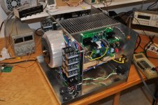
The SIT3X board sets were originally designed for the packaging configuration shown below. The HeatsinkUSA sinks are of the 10.08" series with length of 7" and fin height of 2.5". Over the years that I have used them, I can confirm that the ΔC/W figure of .34C/W/3" is good.
With a little bit of help from quiet PC fans, there is no problem with 150W or more dissipation per heatsink. I am currently using a pair of Noctua NF-F12 fans with 155W dissipation per heatsink and get ΔC=18C. I plan to replace those fans with lower RPM Noctua NF-S12A FLX fans to make it even quieter.
This packing arrangement is very simple to build: 2 x 1/8" aluminum sheets for the back panel and the power supply, and a galvanized steel bottom fabricated by a local sheet metal shop.
Attachments
Last edited:
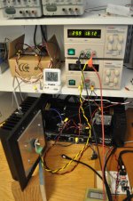
OK - Since I know measurement method is kind of "everything"... Here is how I took the measurements and the conditions under which they were taken. Note - amp has been on for several days. It sits in "free air" on the standard anti-vibration feet. No obstructions over the amp at all. No forced / fan cooling. I re-measured rails and bias again just to be sure. Nice to see it's still rock stable. 😀 After I re-checked bias and checked device temps, the chassis top plate was put back on and the amp was left to sit for ~30 mins before taking heatsink measurements.
1) Cheap Amazon Infrared Thermometer - Zoto PM6530D.
2) Emissivity set to 0.85 (Seems to be roughly correct for black anodized aluminum)
3) Current amp in chassis - BA-3. 6 Output devices per channel. 3 per heatsink. 12 total. Dual mono / fairly tight chassis with dual 400VA transformers mounted to front panel. See pic.
4) 23V76 loaded rails on each channel.
5) Bias - 0A500 (0V110 across 0R22 source resistors)
6) W per device - 11.88
7) W per heatsink - 35.64
8) Ambient Temp - 21.5C
9) Device Temps - (A bit hard to get consistently) ~53C to 54C. Measured @roughly 3 inches away. Temp taken on top of plastic casing.
10) Using ceramic insulators + goop under FETs
11) Heatsink Temps
Left Channel Rear
Left Channel Front
Assuming (I think) worst case...
51 - 21.5 => 29.5C Temp rise
35.64W per heatsink
So... My "real world" situation seems to be ~0.83 C/W
However, this is my first time doing this... Any number of things could be incorrect from the most basic calculations to my measurement technique.
Love to hear some thoughts.

Edited to add: I hit submit too soon. If I use the "K probe" on my DMM, I get lower temp measurements. Is that generally considered more accurate? If so, I can do a set of measurements. Note, the devices are "not even hot" when I give them a touch on the sides, which seems counter-intuitive. Although, I clearly can't touch the junction. The heatsinks are "warm", but definitely not hot at all. I could hold my hand on them all day.
Edited again to add: Should I be trying to measure the temp on the edge of the fins since that's where we would make contact and is the safety concern? The device temps are the operating concern - given. Still learning. Again, happy to help in any way, but I want to be sure my measurements are meaningful.
1) Cheap Amazon Infrared Thermometer - Zoto PM6530D.
2) Emissivity set to 0.85 (Seems to be roughly correct for black anodized aluminum)
3) Current amp in chassis - BA-3. 6 Output devices per channel. 3 per heatsink. 12 total. Dual mono / fairly tight chassis with dual 400VA transformers mounted to front panel. See pic.
4) 23V76 loaded rails on each channel.
5) Bias - 0A500 (0V110 across 0R22 source resistors)
6) W per device - 11.88
7) W per heatsink - 35.64
8) Ambient Temp - 21.5C
9) Device Temps - (A bit hard to get consistently) ~53C to 54C. Measured @roughly 3 inches away. Temp taken on top of plastic casing.
10) Using ceramic insulators + goop under FETs
11) Heatsink Temps
Left Channel Rear
- Upper Left - 43.5
- Upper Center - 47.0
- Upper Right - 48.1
- Center Left - 43.7
- Center Center - 49.7
- Center Right - 51.0
- Lower Left - 43.8
- Lower Center - 46.9
- Lower Right - 48.0
Left Channel Front
- Upper Left - 46.8
- Upper Center - 45.3
- Upper Right - 42.0
- Center Left - 49.6
- Center Center - 47.8
- Center Right - 42.0
- Lower Left - 47.8
- Lower Center - 45.8
- Lower Right - 41.7
Measurement Distance = ~6"
I'll assume right channel behaves similarly, but I can measure if needed.
I'll assume right channel behaves similarly, but I can measure if needed.
Assuming (I think) worst case...
51 - 21.5 => 29.5C Temp rise
35.64W per heatsink
So... My "real world" situation seems to be ~0.83 C/W
However, this is my first time doing this... Any number of things could be incorrect from the most basic calculations to my measurement technique.
Love to hear some thoughts.
Edited to add: I hit submit too soon. If I use the "K probe" on my DMM, I get lower temp measurements. Is that generally considered more accurate? If so, I can do a set of measurements. Note, the devices are "not even hot" when I give them a touch on the sides, which seems counter-intuitive. Although, I clearly can't touch the junction. The heatsinks are "warm", but definitely not hot at all. I could hold my hand on them all day.
Edited again to add: Should I be trying to measure the temp on the edge of the fins since that's where we would make contact and is the safety concern? The device temps are the operating concern - given. Still learning. Again, happy to help in any way, but I want to be sure my measurements are meaningful.
Last edited:
Yes, saw that. Does not include 5U chassis and looking for actual measurements at this time.
Rush
Heatsink 200 X 40 H 210 mm -> 0,28 C°/W (per heatsink, 2 per side)
Heatsink 250 X 40 H 210 mm -> 0,19 C°/W (per heatsink, 2 per side)
Heatsink 300 X 40 H 210 mm -> 0,18 C°/W
Hope this helps 🙂
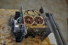
I really like the layout with the fans. It’s very compact and the square footprint looks great. Also much easier to work on with the boards facing outward.
OK - Since I know measurement method is kind of "everything".....
51 - 21.5 => 29.5C Temp rise
35.64W per heatsink
So... My "real world" situation seems to be ~0.83 C/W
However, this is my first time doing this... Any number of things could be incorrect from the most basic calculations to my measurement technique.
Love to hear some thoughts.
...
Note, the devices are "not even hot" when I give them a touch on the sides, which seems counter-intuitive. Although, I clearly can't touch the junction. The heatsinks are "warm", but definitely not hot at all. I could hold my hand on them all day.
....
Yes, those are the numbers I am looking for. How did you measure ambient temperature. Did you use the same instrument? It might be good to start with the amplifier "cold", having been powered off for an hour or more, and measuring the heatsink temperature with the same instrument.
It the heatsink is only warm, then it is probably not near 50C. I have use a simple temperature probe like the one shown in this image:
Attachments
Yes, I used the same device for ambient.
I can power it off for awhile. No problem there.
Sorry for all the edits in the previous post. Is it better / correct to measure the temps at the tip of the fins, since that's where a person (or whatever) would make contact? Are "K-probes" generally considered more accurate? I do have a "meat thermometer" similar to what you've got in your pic. Should I use a dry rub and/or a sauce on the sinks prior to measuring?
Use a thermally conductive "hot" sauce. 😀
Measure at the baseplate. The tips of the fins are likely to be cooler than the baseplate.
Measure at the baseplate. The tips of the fins are likely to be cooler than the baseplate.
I have a feeling that I need a thermostat for active cooling amp in case of failure / human error, so I just got this.
Inkbird Temp Control Thermostat ITC1000 Dual Stage Digital Temperature Switch Controller ℃ ℉ Display Heating Cooling Relay NTC Sensor 3D Printer Freezer Fridge Hatching 110 Volt: Amazon.com: Industrial & Scientific
Inkbird Temp Control Thermostat ITC1000 Dual Stage Digital Temperature Switch Controller ℃ ℉ Display Heating Cooling Relay NTC Sensor 3D Printer Freezer Fridge Hatching 110 Volt: Amazon.com: Industrial & Scientific
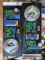
For comparison, here are two channels of Singing Bush ready to be incorporated into the rest of the chassis. I think there is just enough room for the SIT-3X boards + hockey puck SIT itself. I know these heatsinks are good for 120 Watts, without the circular add-on. I'm confident in using them for the Singing Bush so far.
I have a second chassis that is identical to this one, including another pair of circular LED heatsinks to augment the capacity for the SITs. If I understand the operating parameters of the SIT-3X correctly, this should be sufficient for that as well. They may get a little bit hotter, but I think will stay in the 50 to 55 °C region. I will need to look at some options for mounting a pair of power transformers inside this chassis.
I have a second chassis that is identical to this one, including another pair of circular LED heatsinks to augment the capacity for the SITs. If I understand the operating parameters of the SIT-3X correctly, this should be sufficient for that as well. They may get a little bit hotter, but I think will stay in the 50 to 55 °C region. I will need to look at some options for mounting a pair of power transformers inside this chassis.
Attachments
Today I am making measurements of the SIT3X with AC mains input from a Variac. The objective is to measure the class-A Wattage envelope vs. bias current and voltage. It would be nice to know what performance can be obtained with 120W dissipated per heatsink vs. 180W for my prototype as currently adjusted.
Okie Dokie -
I did a few things both to learn a bit and also hopefully to contribute / help.
Here's what I've done.
I grabbed 4 different temp devices, each equipped with physical contact K probes and one with infrared and the K-probe
1) EEVBlog DMM
2) Cheapo Amazon DMM, Viei VC 837
3) Same Infrared thermo from previous posts, but now with K probe attached
4) Meat thermometer.
I let the amp cool for a couple hours until it reached a stable temp. Still above ambient, but it was stable for over 30 mins @ ~23.6C using the average of the two devices that agreed (see below).
I measured the ambient air using all devices - they were close enough. Range from 21.6 to 22C
I taped all the K-probes to essentially the same spot on the heatsink (inside the rear left channel heatsink just above the center output device). I observed the temps every 15 minutes to check agreement (or not) between the devices until the temp showed stable for 30 mins. Two devices tracked, but one DMM was off by a few degrees from the other two. I removed that device from the pool. Just for fun, I probed with the meat thermometer... not worth the effort. It took too long for the temp to rise up and stabilize, but surprisingly it agreed within a few tenths with the device I removed from use. 😀
Either way...
Some "new" results.
Same bias and voltage. Temps taken from inside the chassis on the sink stabilized at an average of 44C (rounding) between the two "good" measurement probes / devices.
I took several measurements on the outside of sinks with hottest point being right at about the point of where the center FET was mounted on that left channel / rear sink. It was ~45C. This is directly against the flat part of the sink where the FETs are mounted. The other 5 positions roughly at the FET mounting positions on the same horizontal axis were between 42 and 44C.
The hottest spot on any tip or edge of the fins was directly out from that spot and measured ~39C. Most of the tips of the sinks sat ~35C, which explains the "not hot" observation from earlier.
On a side note - If I change the emissivity setting on the infrared to 1.00, it comes pretty close to agreeing with the physical K probes.
So....
If we go back to earlier, this may be a bit more in the realm of expectations. I still don't know if the final calc should be made using the tips of the fins or against the "body" of the heatsinks, but we can do both.
35.64W
Highest temp at edge of fins => ~39C
Highest temp on outside of sink against "body" => 45C
Ambient => 22C
Worst case => 23/36 => ~0.64 C/W
Best case => 15/36 => ~0.42 C/W
That's still a far cry from spec. I know NOTHING about true thermodynamics etc. However, a SWAG is that if I upped the bias on the amp with precisely the same orientation, I might not see a linear temp rise.
On a whim, I could up the bias to say 0A75 on each device for a total of 17.82W per device => 53.46W per heatsink. If the math holds, I could expect:
53.4W X 0.64C/W => 34.2C rise +22C ambient => 56C on the flat of the sink
53.4W X 0.42C/W => 22.5C rise +22C ambient => 44.5C on the tips
I had planned at some point to try and get these amps to true "burning amp" status with up to 1A0 bias, which is well within the toroid's general rule for total power of 1/2 to 1/3 and well within the <35W per device general rule...
That would / could be ...
71.38W x 0.64C/W => 46.5 rise +22C ambient => 68.5 ... I think that was "Crikey" hot on the flat of the sinks.
71.38W x 0.42C/W =>30.8 rise +22C ambient => 53 on the tips.
I'd be willing to run a few checks for the sake of the project if it would help. It's on the list anyway. I'd of course stop if temps got out of control / beyond expectations.
Those numbers seem to generally align with what some others seem to have achieved in a similar chassis. I'm sure also that mounting positions and distribution of the heat on the sinks may have something to do with it along with possibly lousy mounting practices... but... those variables can't be altered at the moment.
Thoughts?

Edited to add - Ambient measured ~3" from the sinks is now ~26 C. The temp roughly under the center of the amp is ~29.5C. Like I said... no direct fans or anything near the amp. It's just sitting in the open.
I did a few things both to learn a bit and also hopefully to contribute / help.
Here's what I've done.
I grabbed 4 different temp devices, each equipped with physical contact K probes and one with infrared and the K-probe
1) EEVBlog DMM
2) Cheapo Amazon DMM, Viei VC 837
3) Same Infrared thermo from previous posts, but now with K probe attached
4) Meat thermometer.
I let the amp cool for a couple hours until it reached a stable temp. Still above ambient, but it was stable for over 30 mins @ ~23.6C using the average of the two devices that agreed (see below).
I measured the ambient air using all devices - they were close enough. Range from 21.6 to 22C
I taped all the K-probes to essentially the same spot on the heatsink (inside the rear left channel heatsink just above the center output device). I observed the temps every 15 minutes to check agreement (or not) between the devices until the temp showed stable for 30 mins. Two devices tracked, but one DMM was off by a few degrees from the other two. I removed that device from the pool. Just for fun, I probed with the meat thermometer... not worth the effort. It took too long for the temp to rise up and stabilize, but surprisingly it agreed within a few tenths with the device I removed from use. 😀
Either way...
Some "new" results.
Same bias and voltage. Temps taken from inside the chassis on the sink stabilized at an average of 44C (rounding) between the two "good" measurement probes / devices.
I took several measurements on the outside of sinks with hottest point being right at about the point of where the center FET was mounted on that left channel / rear sink. It was ~45C. This is directly against the flat part of the sink where the FETs are mounted. The other 5 positions roughly at the FET mounting positions on the same horizontal axis were between 42 and 44C.
The hottest spot on any tip or edge of the fins was directly out from that spot and measured ~39C. Most of the tips of the sinks sat ~35C, which explains the "not hot" observation from earlier.
On a side note - If I change the emissivity setting on the infrared to 1.00, it comes pretty close to agreeing with the physical K probes.
So....
If we go back to earlier, this may be a bit more in the realm of expectations. I still don't know if the final calc should be made using the tips of the fins or against the "body" of the heatsinks, but we can do both.
35.64W
Highest temp at edge of fins => ~39C
Highest temp on outside of sink against "body" => 45C
Ambient => 22C
Worst case => 23/36 => ~0.64 C/W
Best case => 15/36 => ~0.42 C/W
That's still a far cry from spec. I know NOTHING about true thermodynamics etc. However, a SWAG is that if I upped the bias on the amp with precisely the same orientation, I might not see a linear temp rise.
On a whim, I could up the bias to say 0A75 on each device for a total of 17.82W per device => 53.46W per heatsink. If the math holds, I could expect:
53.4W X 0.64C/W => 34.2C rise +22C ambient => 56C on the flat of the sink
53.4W X 0.42C/W => 22.5C rise +22C ambient => 44.5C on the tips
I had planned at some point to try and get these amps to true "burning amp" status with up to 1A0 bias, which is well within the toroid's general rule for total power of 1/2 to 1/3 and well within the <35W per device general rule...
That would / could be ...
71.38W x 0.64C/W => 46.5 rise +22C ambient => 68.5 ... I think that was "Crikey" hot on the flat of the sinks.
71.38W x 0.42C/W =>30.8 rise +22C ambient => 53 on the tips.
I'd be willing to run a few checks for the sake of the project if it would help. It's on the list anyway. I'd of course stop if temps got out of control / beyond expectations.
Those numbers seem to generally align with what some others seem to have achieved in a similar chassis. I'm sure also that mounting positions and distribution of the heat on the sinks may have something to do with it along with possibly lousy mounting practices... but... those variables can't be altered at the moment.
Thoughts?
Edited to add - Ambient measured ~3" from the sinks is now ~26 C. The temp roughly under the center of the amp is ~29.5C. Like I said... no direct fans or anything near the amp. It's just sitting in the open.
Last edited:
5U/400 will be damn hot with 120W of heat per side ..... it isn't much better than regular ( at least to me ) 4U/400
that's more 5U/500 territory
though, 5U/400 will work for 120 per side, with Babysitter
note : not even a single iota against Modushop, that's simple Physics - not even Gianluca can't pack 2 cases in space of one, without resorting to forced cooling
that's more 5U/500 territory
though, 5U/400 will work for 120 per side, with Babysitter
note : not even a single iota against Modushop, that's simple Physics - not even Gianluca can't pack 2 cases in space of one, without resorting to forced cooling
If I were starting completely from scratch, and if I'd have known the 5U / 500 existed, I would have snagged them. 😀 Gives tons of room to experiment.
There's also the saying... If a bullfrog had wings, he wouldn't bump his rump every time he jumped.
Edited to add another brain fart question... would anyone see a reason to attempt to thermally couple the two heatsinks together on each side? I'm not sure if I could do it, but....
There's also the saying... If a bullfrog had wings, he wouldn't bump his rump every time he jumped.
Edited to add another brain fart question... would anyone see a reason to attempt to thermally couple the two heatsinks together on each side? I'm not sure if I could do it, but....
Last edited:
naah
it's all the same thermal compartment ( one volume in which is heat contained), which is dominant
it could be an issue with uneven dissipation of parts in symmetric position in circuit, but in that case you already have deeper problem, which even absolute cooling symmetry can't salvage
it's all the same thermal compartment ( one volume in which is heat contained), which is dominant
it could be an issue with uneven dissipation of parts in symmetric position in circuit, but in that case you already have deeper problem, which even absolute cooling symmetry can't salvage
Heat flow is driven by temperature difference. If each heatsink already has an active device dissipating about the same power, they will both be at about the same temperature so thermally coupling them together won't cause any heat transfer. If one was cooler than the other, it would help.
Rate of heat transfer and dissipation is dependent on the temperature differential.
At low temperature differential, the heat sink will not dissipate heat as efficiently as at higher temperature differential.
For accurate C/W at a certain temperature differential, it needs to be measured at that temperature differential.
I believe that heatsink C/W provided by manufacturers is usually for higher differential than what we usually allow. So the rated C/W is not conservative for our use.
Fantastic comments. Thanks to all. Lynn, apologies if I've hi-jacked the thread a bit.
ZM - Apologies if I implied there was a problem. There is not. Amp runs flawlessly. I can see how you'd think I may have had an issue given my general dodoness.
I've got the amp biased up to 0A75 now. It is clearly a "hot box". It's been sitting at that bias for about 45 min now, and I've got the offset re-set to below 1mV on each channel. It's wild how rock steady this design is.
Ben, that's very interesting. I admit to not following 100%. However, I'm a visual / slow learner. I'll "get it" eventually. 😀
Lynn - for your interest.
At 0A75 (see previous post for general expectations)... Using the same K-probe as the measurement tool, I am getting:
Average hot area directly on the sink ~51.x C
Edge of fins right on same fin area as hot area on sink - ~44.x C
Coolest areas are ~4 to 5 C cooler on edges.
Ambient in the room further away is still ~22C
Ambient a few inches from the amp has now risen to ~27C (and slowly climbing)
Using Papa's fully calibrated hand method referenced below, I'd say that I am just below Blimey hot. I can still hold my hands on the sinks for as long as I want. The more tender inner part of my forearm is more sensitive, but I can still rest it on the sink. My brother has a Forte 4A - it feels in that neighborhood.
I can tell just by getting near it to tweak the bias / offset that the amp is running much warmer at this higher bias though. The data is here, but I don't know which ambient is most appropriate to use and whether to calc based on the temp of the main body of the sink or the tips of the fins.
Using the infrared to try and get a rough shot on the devices, I am showing ~55C. The infrared still reads a touch higher than the physical K probes though.
Either way, I think these sinks would be around the limit for where most people may want them at this power. I'll ramp it up a bit more tomorrow. I just have to listen to it at the higher 0A75 bias though for a while before tweaking it again. 😀
"Blimey hot is 10 sec hands on = 45c
Crikey hot is 5 seconds = 50c
Bloody hot is 2 seconds = 55c
X*?@! is 60c"
My point was that power dissipation vs temperature differential is not linear. As temperature differential increases, power dissipation increases at a higher rate.
So a higher temperature differential should give a lower C/W.
So a higher temperature differential should give a lower C/W.
Today's bench test results: I experimented using a Variac to change the AC mains voltage to the SIT3X prototype. I adjusted the Variac to obtain the secondary voltages commonly available from AntekInc.com. At those voltages and several different OS bias currents I looked at the distortion spectra at 1W, 25W, and a variety of higher wattages into an 8R load. I will not go into the details of all of the combinations, but here what looks like a good candidate for 120W per heatsink power dissipation:
Operating Point:
Caveat: I have not yet done any listening tests with this configuration.
Operating Point:
- 32Vrms secondary voltage
- V(J1d,M1d) = 73.5V drain to drain voltage across the OS FETs
- 1.63A OS bias current
- 120W dissipation for both FETs
- 1W 8R THD=.029% H2/H3=6dB
- 25W 8R THD=.265% H2/H3=-6.6dB
- 30W 8R THD=.311% H2/H3=-9.5dB harmonic falloff good
- 36W 8R THD=.376% H2/H3=-13dB harmonic falloff good
- 42W 8R THD=.51% H2/H3=-15dB harmonic falloff getting crummy
Caveat: I have not yet done any listening tests with this configuration.
- Home
- Amplifiers
- Pass Labs
- The SIT-3X Amplifier