Good news for 5U 400mm SIT3X builders:
I have adjusted both channels of my prototype for 32Vrms transformer secondary voltages and a power dissipation into the heatsink of about of 120W per channel. The 2SK182ES SIT operating point was adjusted to Vds=46V Id=1.63A. The Xpot was adjusted for the M1 PFET acting as a CCS at 1W into an 8R load. The FCFE bias currents remained constant with the change in rail voltages.
Bench measurements show some increase in harmonics. The class-A and clipping envelopes are decreased. The channels are still very good to about 36W into 8R, higher into 4R.
I am currently doing listening tests connected to the Variac, and it sounds very good.
🙂 🙂 🙂 🙂
Thank you for making this available and all the incredible work. I may use this as an excuse to get a more robust set of heatsinks, but knowing it can function as you've intended at a lower power rating suitable for the 5U 400 is wonderful news. I've read and re-read the original thread a few times and even again today to understand the journey and the thought process. The measurements and least squares analysis and modeling to determine the "sweet spots" was inspiring along with following your nose to determine the factors for 3rd order cancellation. Each time I read it, I learn just a bit more.

Thank you for making this available and all the incredible work. I may use this as an excuse to get a more robust set of heatsinks, but knowing it can function as you've intended at a lower power rating suitable for the 5U 400 is wonderful news. I've read and re-read the original thread a few times and even again today to understand the journey and the thought process. The measurements and least squares analysis and modeling to determine the "sweet spots" was inspiring along with following your nose to determine the factors for 3rd order cancellation. Each time I read it, I learn just a bit more.
Actually, the sweet spot analysis was more important for the SIT-2 mu-follower circuit than for the SIT-3 SIT/PFET follower circuit. However, the sweet-spot analysis might play a role in choosing the SIT operating point in the SIT3X. It turn out that when the Xpot is adjusted for the PFET operating as a CCS, the SIT Vds (one parameter of the operating point) can be chosen over a large range of voltages without significantly impacting the amplifier class-A or clipping envelopes. The choice of SIT Vds has an effect on the H2/H3 ratio. I will present some plots about this at some point in the future.🙂 🙂 🙂 🙂
...
The measurements and least squares analysis and modeling to determine the "sweet spots" was inspiring along with following your nose to determine the factors for 3rd order cancellation. Each time I read it, I learn just a bit more.
I had seen your transition in chosen topologies through the thread based on what you wanted to achieve. 🙂 Your analysis "fits" (see what I did there?  ) with some memories of my grad research work. So, I could wrap my head around that piece of your work even without understanding key functions of the devices in the circuit. Weird, I know...
So, is it correct in layperson's terms that with the current SIT-3/PFET follower that:
The "proper" operating points for the unobtainium SITs can potentially be achieved across a wider range of individual SITs while still allowing Xpot to be used to adjust H2/H3 ratio and maintaining the Class-A envelope? i.e. It's forgiving, in a sense?
Would this feature/behavior also allow the potential use of SITs like the THF-51 family?
The latter question may be out of scope. If so, apologies.
) with some memories of my grad research work. So, I could wrap my head around that piece of your work even without understanding key functions of the devices in the circuit. Weird, I know... So, is it correct in layperson's terms that with the current SIT-3/PFET follower that:
The "proper" operating points for the unobtainium SITs can potentially be achieved across a wider range of individual SITs while still allowing Xpot to be used to adjust H2/H3 ratio and maintaining the Class-A envelope? i.e. It's forgiving, in a sense?
Would this feature/behavior also allow the potential use of SITs like the THF-51 family?
The latter question may be out of scope. If so, apologies.
The Xpot adjusts a balance between the amplification (transconductance) of the SIT and the PFET. It does not work between an NFET and a PFET. I still do not really understand exactly what is going on with the Xpot. Most of my listening has been done with the Xpot adjustment where the PFET is operating as a current source at 1W, and where the SIT is in control of the sound.
Assuming that the front-end (FE) is relatively neutral, the H2/H3 ratio is related more to the operating point of the SIT, as characterized by the sweet-spot measurements.
Yes, it appears the a wide range SITs might be used in the SIT3X, but the SIT Vgs range might be different enough to require some circuit changes.
Does anyone have a datasheet for the THF-51? How do their characteristics compare to the Tokin 2SK182ES?
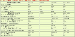
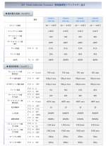
This might help.
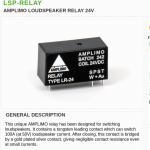
Thank you AMPLIMOS one stage amplifiers amplificatori audio monostadio
Thank you AMPLIMOS one stage amplifiers amplificatori audio monostadio
Attachments
Last edited:
I sent Woofertester a pair of my THF-51S for measurement. I believe he also measured the 2SK182, but I am unsure about the 2SK182ES. I'll shoot him a note to see if he can offer some insights. I trust his measurements.
differences between them are much smaller than importance of fact of having any of them, especially if some NFB is wrapped around, and source follower is in case
relays in speaker hot
I don't care for that difference someone can hear when including decent relays in speaker line
life is too short ..... or, I'm choosing other areas to fully develop my OCD
Le freak, c'est Chic
Attachments
The Tokin parts that I curve traced are the 2SK182ES. The package looks just like the THF-51S.
Last edited:
The SIT3X PCBs have been fabricated and shipped. I expect to receive them Friday Sept 4. Unless something unexpected occurs, I expect the cost per board set to be about $25 plus shipping to you. The board set includes 7 boards total: 2x FCFE, 1x OSleft, 1x OSright, 2x PScaps1, and 1x PScaps2.
I am still working on the BOMs. There probably needs to be a different BOM for the power supply, depending on the chassis and heatsink capacity being used.
I am still working on the BOMs. There probably needs to be a different BOM for the power supply, depending on the chassis and heatsink capacity being used.
Hello @Ihquam
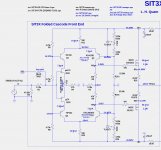
could you put please latest schematics online, or give a link to actual post?
JP
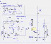
Here are schematics for the FCFE and the OS. Best guess at the BOMs will be posted shortly. I hope to test the PCBs and BOMs by ordering parts using the BOMs and populating the new PCBs with them before posting the "final" BOMs and shipping PCBs to forum members. In this way I can test the correctness of both the new PCBs and the BOMs.
Attachments
- Home
- Amplifiers
- Pass Labs
- The SIT-3X Amplifier