Karsten, I tried to better understand your idea with a (almost) technical drawing: at first sight i thought: no, it doesn't work, it is unstable - just a minimum off center of the spring to lose the balance and make it rise (or lower) as it likes, without control. To be discarded.
Then I thought: but if we attach the spring off-center, where we need it (adjustable), we can use this tendency to adjust the VTF, or even eliminate the CW.
Bingo, Karsten.
Perhaps the same principle can also be used with the single lever, by moving the blade joint seat, instead of acting on the line . Far easier to tune.
c
Hi, guys
Totally off topic but perhaps some aspects of this tonearm can be adapted, seems to solve many of the problems that plague most tonearms. For the fertile minds here !! Worth a look and perhaps worthy of its own (DIY) thread.
Integrityhifi TRU-GLIDER Pendulum Tonearm
7L5qWTLCNCGNmTIumkbMd-e0m9Eid7LQ1FKESUWDsPR3OSmtA
Joe
mousetrap tech 2
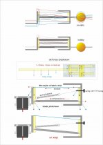
I was thinking of a vector breakdown done long ago to explain the need and the behavior of the parallelogram on LC.
Yesterday hypotheses may be further simplified, and look more like something buildable
carlo
More interesting thoughts Carlo.
There are constant force/tension springs, but i am not sure if they are made small enough or inexpensive, which would put aside any worry over VTF variation with the conventional spring, however small that might be.
I am playing with small bits of Mylar (drawing film) i have while considering their use for flexural hinges and whilst i see how the forces work on your diagram, i feel that solution might be more vulnerable and less rugged than the two solid struts.
errata corrige - sorry, the spring must be tied at least at blade level, or under not to loosen the upper side.
such spring are not so difficult to find in the scrap bin, or simply to diy, wrapping some thin steel wire.
c
such spring are not so difficult to find in the scrap bin, or simply to diy, wrapping some thin steel wire.
c
mousetrap tech 2
I was thinking of a vector breakdown done long ago to explain the need and the behavior of the parallelogram on LC.
Yesterday hypotheses may be further simplified, and look more like something buildable
carlo
The upper mylar strip is compressed and not pulled, so it would break down.
The spring should be attached under the knife edge.
Last edited:
Hi Alighiszem, by now I am so old and dumb that you made me doubt, and I had to make a quick mockup to verify
A - lifted - the parallelogram is just a cantilever = rope (or mylar) under tension
B - tracking -- the parallelogram is still a cantilever, leaning on the stylus springiness = again rope (or mylar) under tension
C - smashed down beyond stylus spring capability - weight completely on disk = only now rope (or mylar) compressed as you said.
On tracking condition B the parallelogram seems OK, isn't it?
maybe i'm not so old. - carlo
Attachments

Last edited:
Smash down
Ciao Carlo,
I guess your small mock-ups nicely illustrate the real problem with the proposed approach: there is nothing that prevents the collapse of the whole parallelogram construction. Inevitably one would end up with situation C and damaged albums or worse 😱
saluti, Mark
Ciao Carlo,
I guess your small mock-ups nicely illustrate the real problem with the proposed approach: there is nothing that prevents the collapse of the whole parallelogram construction. Inevitably one would end up with situation C and damaged albums or worse 😱
saluti, Mark
Ciao Carlo,
I guess your small mock-ups nicely illustrate the real problem with the proposed approach: there is nothing that prevents the collapse of the whole parallelogram construction. Inevitably one would end up with situation C and damaged albums or worse 😱
saluti, Mark
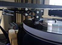
Hi Mark, i am particularly interested in this bit as a move forward from my current version, pic attached. My current parallelogram has BB joints as you can see and these alternatives seek to avoid those with their play etc.
I think two things need remembering from previous posts in addition to Carlos most recent explanation, first that there will also be either a tension spring or a counterweight, two options to balance the cartridge weight and adjust VTF, so in all normal circumstances the fact that VTF remains positive always keeps the top in tension, second the top line would only go out of tension if you pushed the cartridge down and or unloaded the spring/counterweight. However, with finger trouble that might happen, but it might also be less vulnerable with a top line that can compress.
BTW, i stuck mass loaded vinyl to the sides of the rail carriage, cannot say i noticed a specific difference but the whole still sounds really rather nice and i look forward to further improvements. The running of my wiring is currently the most unpredictable thing and needs refinement, i think a loose plait might be something to try, or several ties perhaps.
mike
Attachments
Couldn't resist: added the spring (well a rubber band) to work as CW, and behaves the same as previously; and another mock up for the first idea - one lever+2 strings - This one seems easier to build and calibrate, (especially the azimuth). Promising, imo.
Ciao bambo, that mock up "nicely illustrates" simply that the upper rope, under normal tracking conditions is under tension, not compressed.
...there is nothing that prevents the collapse of the whole parallelogram construction:
For sure, exactly as any pivoted without a lifter, but from a lower height. Do you usually put lifters on your mock ups? not me
carlo
always nicer that arm, Mike.
Attachments

I can see it with new rails (something like Carlos) and a mousetrap (i.e. a parallelogram without BB's) already! - actually it will of course be a new arm by then with much influence from all your excellent suggestions.Couldn't resist: added the spring (well a rubber band) to work as CW, and behaves the same as previously; and another mock up for the first idea - one lever+2 strings - This one seems easier to build and calibrate, (especially the azimuth). Promising, imo.
Ciao bambo, that mock up "nicely illustrates" simply that the upper rope, under normal tracking conditions is under tension, not compressed.
...there is nothing that prevents the collapse of the whole parallelogram construction:
For sure, exactly as any pivoted without a lifter, but from a lower height. Do you usually put lifters on your mock ups? not me
carlo
always nicer that arm, Mike.
Hi Carlo,
thank you, now I get the point you're aiming for. Should have read more before jumping in 😉 Great inspiration you are providing! Particularly with all the small steps you actually make and demonstrate to share. I like it a lot. Best of luck with your construction adventures!
Mark
Hi Mike,
I think that the problems that you are experiencing with your arm cables is simply due to them being too heavy a gauge. I initially had the same problem with my arm cables. My current arm cables are made from very thin magnet wire. The wire is 0.08mm, which is 40 gauge. I twist 4 strands together then use 2 for the positive and 2 for the negative. This twisted quad had excellent shielding. Each quad is very thin. I run one quad per channel.
I tried using just 2 strands but the sound was a bit thin. I also tried 6 strands. I could not hear any difference between the 4 strand and 6 strand cables but the 6 strand was notably stiffer.
I hope this helps.
Niffy
Many thanks for that suggestion Niffy, I used Litz wire off Amazon or equivalent, it seems quite thin but i have no idea what gauge each strand is or the overall stiffness.
Did you find a good value UK supplier of Magnet wire please or do you not feel source is critical?
many thanks
Mike
Did you find a good value UK supplier of Magnet wire please or do you not feel source is critical?
many thanks
Mike
Earphone wires work very good. I have used wires from cheap philips earphone they were very think, colour coded and flexible.
Regards
Sachin
Regards
Sachin
The litz wire I initially used had 40 strands of 0.04mm enameled wire in a silk sheath. This has 10 times the cross section of copper plus the weight of the outer sheath compared to my current wire. My quad wire has an overall diameter of about 0.2mm, and that includes both positive and negative conductors. My wire actually has a higher stiffness to mass ratio than the litz meaning that it can make longer unsupported loops which makes cable dressing much easier. As my wire is so light it's overall stiffness is probably about a third that of the litz plus you don't have the weight of the wire pulling on the carriage. Of course you have to double this up for the litz as you need two runs per channel.
Niffy
Niffy
The litz wire I initially used had 40 strands of 0.04mm enameled wire in a silk sheath. This has 10 times the cross section of copper plus the weight of the outer sheath compared to my current wire. My quad wire has an overall diameter of about 0.2mm, and that includes both positive and negative conductors. My wire actually has a higher stiffness to mass ratio than the litz meaning that it can make longer unsupported loops which makes cable dressing much easier. As my wire is so light it's overall stiffness is probably about a third that of the litz plus you don't have the weight of the wire pulling on the carriage. Of course you have to double this up for the litz as you need two runs per channel.
Niffy
Many thanks for both Niffy, all very clear thanks, my litz is .5mm diameter so the comparison is obvious. i am sure you've also listened carefully and not found a move away from Litz a downgrade in audible performance, i shall do this soon now, i shall search a bit further for suppliers as the shortest they have through this link is approx 1100m!
Hi Mike,
Are you in the UK? If you are I can send you a length. PM me your address.
Niffy
That's very kind Niffy, however don't worry now as i just ordered some very close in size, it will last me many lifetimes!
thanks again, mike
- Home
- Source & Line
- Analogue Source
- DIY linear tonearm