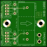
Ordered boards today. They ended up looking suspiciously similar but a lot less pretty than SB's 🙂
How will you mount the two pairs of power transistors on the heatsinks? I do not understand how they will fit, being so close to each other.
What is probably needed is also some delay at power-on, and why not an other delay on the rear input pcb, to switch the input relay only after some delay, kind of input mute... And some power supplies monitoring, can be the input delay, no fault alarm until both protect and power supplies voltages are stabilized...
Would something like work?:
"220V Class A Amplifier Power Delay Soft Start Temperature Protection Board"
220V Class A Amplifier Power Delay Soft Start Temperature Protection Board | eBay
It has a 220 to 12V transformer, NTC resistors to dampen start current, 5 second delay of two 30A relays, 75 centigrade sensors.
Last edited:
Yes, that cover the Power-On, Softstart and over temp protection. Exacty what I was planning to use, but with solid-state relay instead of actual relay (smaller) and also the Solid State relays are zero-crossing (switch on at the 0Vac point of the ac waveform.
Just need to add the protection pcb with current sensing and crowbar and you have a complete DartZeel 😉
Here again an othe Goldmund protection schematic. A lot of op-amp, comparators, but from count, the DartZeel has about 20 op-amp on it...
Naturally there are some differences, the Goldmund has the Left and Right channels monitored on the same schematic, the Goldmund current sensors are on the power supply output, so are measuring DC current, the DartZeel is measuring DC+AC, so probably need some form of active op-amp rectifier, but it gives us an idea...
Attachments
How will you mount the two pairs of power transistors on the heatsinks?
One pair faces the other way and goes underneath the board, you can see the cutouts for the screws. Same with the bias spreader.
Not sure if it's ideal, but the original was developed with the intention to offer an upgrade service for series 1 owners, that's why the board shares the same footprint with series 1.
From what i gather, it is SB's intention to emulate the original as closely as possible and to this end he is trying to achieve the same with the protection circuit too.
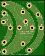
Did a capacitor bracket pcb, with 1oz copper top/bottom = 2oz, for test purpose and prototype quick assembly. I'll use two pcb per cap banks, that will equal to 4oz copper. I won't try a 250Amp crowbar on it, but it will make the assembly of the prototype much easier and faster...
The final pcb will be with a Yellow silkscreen.
The final pcb will be with a Yellow silkscreen.
Attachments
Last edited:
For those that bought the PCB from me, DartZeel Ver2 and Ver1 2mm/2oz amplifier PCB ordered...
SB
SB
The cap board looks very nice. Just wish there was a simple way to make it out of copper as it should be. No idea if it makes an audible difference, but this is probably the part of the Dartz esthetics i like the most.
So how do your two boards differ, analog_sa and Algar_emi? They look rather similar, but I notice Analog has One larger capacitor C100 while Algar has two MKP10, eg. But I guess the function will be the same, or..?
Will you make more boards after your first batches have arrived? (I would also like to build one of them)
Will you make more boards after your first batches have arrived? (I would also like to build one of them)

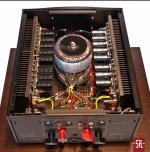
Is this clone true to the original when it comes to placement of protection circuits and other components underneath the main transformers? Are there really 2x2 diode bridges on the original?
But should not the big electrolytic capacitors be closer to the mainboard/output transistors? Is this really an optimal placement (on the original)?
But should not the big electrolytic capacitors be closer to the mainboard/output transistors? Is this really an optimal placement (on the original)?
Attachments
Last edited:
Better design?
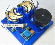
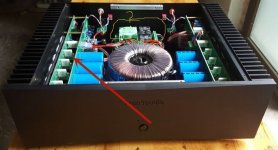
Is not this a better design/placement of electrolytic capacitors? (close to the output transitors) (Hegel)
..or another chinese clone amplifier.
And what is better? A few huge ones or many, smaller?
Is not this a better design/placement of electrolytic capacitors? (close to the output transitors) (Hegel)
..or another chinese clone amplifier.
And what is better? A few huge ones or many, smaller?
Attachments
Last edited:
Take a close look - they are located in the original close, on my clone 10-12 cm, the power wires from the capacitors to the board, but the diodes are farther away mounted on the partition for cooling.
No idea really, but I suspect a very simple bridge per transfo. The capacitor banks are so big, and also the presence of the Crowbar protection suggest a big, tough rectifier bridge. I like the big Vishay 35MB100A, with 35A, 1KV specs. And Pass use it a lot in some of his supplies. Pass like slow recitifier like this one.
Yes I know of the brackets on Tabeo, but only Chinese can buy from this site...
And yes analog_sa I also believe that a lot of little details of the original, like these copper cap bracket may explain the difference in sound from a clone and the original.
One member that has the original and made two clones said that the original has better imaging, and sounds better...
Nice find. Probably gold plated brass. Certainly reasonably priced. Is this a Taobao reseller?
So how do your two boards differ
Mostly in the libraries used, SB's are much prettier. I saw no point in having two crappy Wimas in parallel as used in the original and made space for the single caps i am likely to use. Not nearly enough space for anything really nice but sufficient at least for Auricaps with the option for BG-N i currently use.
Anyway, unimportant, as the boards i ordered are just for testing. No one really knows if this amp will be worth keeping, it's an experiment. Until an owner has taken and published pics of the real thing we can only speculate what exactly goes inside.
I saw no point in having two crappy Wimas in parallel as used in the original and made space for the single caps i am likely to use.
 I'm with you on this one
 Keep us posted 😀Anyway, unimportant, as the boards i ordered are just for testing. No one really knows if this amp will be worth keeping, it's an experiment. Until an owner has taken and published pics of the real thing we can only speculate what exactly goes inside.
- Home
- Amplifiers
- Solid State
- Dartzeel amp schematic - build this?