https://frank.pocnet.net/sheets/020/1/12AX7S.pdf
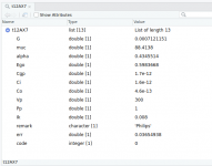
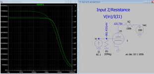
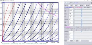
Ayumi is the only one that models grid current Ig/Ia plot ok but for some reasons it fails to plot Vg/Ig which is the input impedance of the tube. Not sure which brand 12ax7ay it referred to in the model so I cannot verify the accuracy of the plots, but verify quite well against circuits around on the net.
Using this data as a hint I built Mazda 12ax7s model, successfully plot input impedance curve for various grid bias voltage so see how it goes.
Well done, Koonw!
I guess this model is very interesting for all guitar amps, as in such applications, the 12AX7s often are overdriven.
I'm working on JJ ECC83S and Tung-Sol 12AX7 measurements. LTspice models will follow...
all the best, Adrian
Thanks for that Koonw.
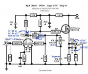
Do you think this 12AX7_MAZ model will be accurate for simulating contact-potential bias? For instance, Eli Duttman's RCA-style phono stage uses the second stage with contact-potential bias, with the 12AX7 cathode grounded and a large (20M) grid leak resistor. Would this model simulate that accurately?
Do you think this 12AX7_MAZ model will be accurate for simulating contact-potential bias? For instance, Eli Duttman's RCA-style phono stage uses the second stage with contact-potential bias, with the 12AX7 cathode grounded and a large (20M) grid leak resistor. Would this model simulate that accurately?
Attachments
Looking in RStudio, it appears to be Philips.https://frank.pocnet.net/sheets/020/1/12AX7S.pdf
Ayumi is the only one that models grid current Ig/Ia plot ok but for some reasons it fails to plot Vg/Ig which is the input impedance of the tube. Not sure which brand 12ax7ay it referred to in the model so I cannot verify the accuracy of the plots, but verify quite well against circuits around on the net.
Attachments
Thanks Adrian. I'm looking forward to your 12AX7/ECC83 model.I'm working on JJ ECC83S and Tung-Sol 12AX7 measurements. LTspice models will follow...
all the best, Adrian
Thanks for that Koonw.
Do you think this 12AX7_MAZ model will be accurate for simulating contact-potential bias? For instance, Eli Duttman's RCA-style phono stage uses the second stage with contact-potential bias, with the 12AX7 cathode grounded and a large (20M) grid leak resistor. Would this model simulate that accurately?
Hi rongon
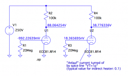
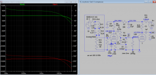
I doubt that Koonw's 12AX7_MAZ model will deliver an accurate bias point. It does not consider the "Anlauf" current (initial velocity grid current), which leads to a voltage drop up to -1V across a 20 Mohm resistor.
See my graph attached, I did a short comparison with and without "Anlauf" current. I used a ECC81 as I have not generated an ECC83 model yet - but this will follow soon 😉.
cheers, Adrian
Attachments
Riaa eq out is same for Ayumi and 12AX7_MAZ with original RCA riaa schematic and does not required any alteration of timing component value as in Eli's. This is true even with 2nd section is disconnected, the output of 1st stage is same. So this implied the output Z is no difference. If the cathode bias is used as in original 12AX7_MAX has about 0.7dbs higher that is all. But when you use grid leak bias the value of R2 resistor 20M in Eli need to be change 120Meg. This is because my model has much lower input impedance because grid current is model. Eli's need to alter riaa timing components I find that is not needed. In actual circuit R2 could be different also, but Eli altered the timing components (values depend on which tube in used) instead of increase R2 value that is all.Thanks for that Koonw.
Do you think this 12AX7_MAZ model will be accurate for simulating contact-potential bias? For instance, Eli Duttman's RCA-style phono stage uses the second stage with contact-potential bias, with the 12AX7 cathode grounded and a large (20M) grid leak resistor. Would this model simulate that accurately?
P/S The model is still under testing. I reduced VgOff from -0.7v to -0.1v then I can use 20M for R2, as the input impedance is increased so the combined Z is about 680k as original. The accuracy of input Z is important.
Last edited:
Huh.
It's amazing what you guys are doing for something as silly as vacuum tubes -- but I like it! 😀
I figure contact-potential bias has to be really difficult to model accurately.
I didn't think the RIAA eq would change much, but just getting a contact-potential biased model to show bias properly is definitely a challenge.
Keep up the great work you guys. Much appreciated by us tube aficionados.
--
I have remodeled 12ax7_maz the grid current so that input impedance becomes more accurate. When 20M as grid resistor, the total input Z is about 680k (700k//20Meg=680k). VgOff is not changed to increase input Z as this is the grid contact bias that already assume to have correct plate voltage as found in practical circuit measurement. Instead other parameters such as IGA IGB and IGC and IGEX is changed to achieve the target Z.
Code:
**** 12AX7_MAZ ** Advanced Grid Current **********************************
* Created on 05/26/2020 09:28 using paint_kit.jar 3.1
* [URL="http://www.dmitrynizh.com/tubeparams_image.htm"]Model Paint Tools: Trace Tube Parameters over Plate Curves, Interactively[/URL]
* Plate Curves image file: 12ax7-maz.png
* Data source link:
*----------------------------------------------------------------------------------
.SUBCKT 12AX7_MAZ 1 2 3 ; Plate Grid Cathode
+ PARAMS: CCG=1.6P  CGP=0.46P CCP=1.7P
+ MU=100 KG1=2354.4 KP=771.4 KVB=63.48 VCT=0.7102 EX=1.658
+ VGOFF=-0.7 IGA=0 IGB=0.01 IGC=15 IGEX=1.6
* Vp_MAX=500 Ip_MAX=3.5 Vg_step=0.5 Vg_start=1 Vg_count=14
* Rp=4000 Vg_ac=55 P_max=1.1 Vg_qui=-48 Vp_qui=300
* X_MIN=37 Y_MIN=13 X_SIZE=767 Y_SIZE=538 FSZ_X=1296 FSZ_Y=736 XYGrid=false
* showLoadLine=n showIp=y isDHT=n isPP=n isAsymPP=n showDissipLimit=y
* showIg1=y gridLevel2=y isInputSnapped=n
* XYProjections=n harmonicPlot=n dissipPlot=n
*----------------------------------------------------------------------------------
E1 7 0 VALUE={V(1,3)/KP*LOG(1+EXP(KP*(1/MU+(VCT+V(2,3))/SQRT(KVB+V(1,3)*V(1,3)))))}
RE1 7 0 1G  ; TO AVOID FLOATING NODES
G1 1 3 VALUE={(PWR(V(7),EX)+PWRS(V(7),EX))/KG1}
RCP 1 3 1G   ; TO AVOID FLOATING NODES
C1 2 3 {CCG} ; CATHODE-GRID
C2 2 1 {CGP} ; GRID=PLATE
C3 1 3 {CCP} ; CATHODE-PLATE
RE2 2 0 1G
EGC 8 0 VALUE={V(2,3)-VGOFF} ; POSITIVE GRID THRESHOLD
GG 2 3 VALUE={(IGA+IGB/(IGC+V(1,3)))*(MU/KG1)*(PWR(V(8),IGEX)+PWRS(V(8),IGEX))}
.ENDS
*$
Attachments
Here is the 12ax7 model based on Philips, grid current parameter is ported from Mazda's (with only minor adjustment) and it gives the same results. (Don't bother about grid parameters in Paint snapshot that was before the adjustment)
Code:
**** 12AX7_PL ** Advanced Grid Current **********************************
* Created on 05/25/2020 18:38 using paint_kit.jar 3.1
* [url=http://www.dmitrynizh.com/tubeparams_image.htm]Model Paint Tools: Trace Tube Parameters over Plate Curves, Interactively[/url]
* Plate Curves image file: 12ax7-pl.png
* Data source link: [url]https://frank.pocnet.net/sheets/030/e/ECC83.pdf[/url]
*----------------------------------------------------------------------------------
.SUBCKT 12AX7_PL 1 2 3 ; Plate Grid Cathode
+ PARAMS: CCG=1.6P  CGP=1.6P CCP=0.33P
+ MU=100 KG1=1684.48 KP=866 KVB=181.44 VCT=0.5091 EX=1.431
+ VGOFF=-0.7 IGA=0 IGB=0.01 IGC=15 IGEX=1.76
* Vp_MAX=375 Ip_MAX=5 Vg_step=0.5 Vg_start=1 Vg_count=11
* Rp=4000 Vg_ac=55 P_max=1.1 Vg_qui=-48 Vp_qui=300
* X_MIN=20 Y_MIN=15 X_SIZE=841 Y_SIZE=544 FSZ_X=1296 FSZ_Y=736 XYGrid=false
* showLoadLine=n showIp=y isDHT=n isPP=n isAsymPP=n showDissipLimit=y
* showIg1=y gridLevel2=y isInputSnapped=n
* XYProjections=n harmonicPlot=n dissipPlot=n
*----------------------------------------------------------------------------------
E1 7 0 VALUE={V(1,3)/KP*LOG(1+EXP(KP*(1/MU+(VCT+V(2,3))/SQRT(KVB+V(1,3)*V(1,3)))))}
RE1 7 0 1G  ; TO AVOID FLOATING NODES
G1 1 3 VALUE={(PWR(V(7),EX)+PWRS(V(7),EX))/KG1}
RCP 1 3 1G   ; TO AVOID FLOATING NODES
C1 2 3 {CCG} ; CATHODE-GRID
C2 2 1 {CGP} ; GRID=PLATE
C3 1 3 {CCP} ; CATHODE-PLATE
RE2 2 0 1G
EGC 8 0 VALUE={V(2,3)-VGOFF} ; POSITIVE GRID THRESHOLD
GG 2 3 VALUE={(IGA+IGB/(IGC+V(1,3)))*(MU/KG1)*(PWR(V(8),IGEX)+PWRS(V(8),IGEX))}
.ENDS
*$
Attachments

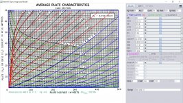
12AT7 proved to be a difficult challenge for Paint Tool as it's so non-linear with Mu range from 45 to 95, attached is snapshot with a single u=60 is a lot to be desired, anyone want the models?
Attachments
Very nice fit, indeed! Thank you!Here is the 12ax7 model based on Philips, grid current parameter is ported from Mazda's (with only minor adjustment) and it gives the same results. (Don't bother about grid parameters in Paint snapshot that was before the adjustment)
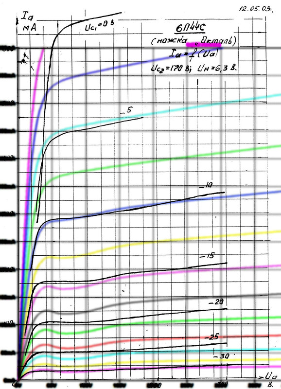
I have tried to make a code for Russian tube 6П44С / 6P44S using pentode paint tools. This is the code I got:
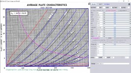
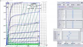
This is how it fits - not the best, but I couldn't make it fit better. Please note that I have Vg with 2.5V steps (color lines), while original has 5V steps. Curves are OK for 0, 5, 10, 15 and 30V, and 20 and 25 are not good. How to fix this?
Which parameters shall I try to adjust to make this kink smaller and to make less slope at the coordinate system origin?
Code:
*----------------------------------------------------------------------------------
.SUBCKT 6P44S_P P G2 G K ; LTSpice tetrode.asy pinout
* .SUBCKT 6P44S_P P G K G2 ; Koren Pentode Pspice pinout
+ PARAMS: MU=6.553 KG1=1637.7 KP=21.85 KVB=1350 VCT=0.032 EX=1.779 KG2=2280 KNEE=3.713 KVC=2.57
+ KLAM=2.32E-6 KLAMG=3.645E-4 KNEE2=20 KNEX=30  KNK=-0.044 KNG=0.006 KNPL=50 KNSL=11 KNPR=120 KNSR=29
+ CCG=22P CGP=9P CCP=1.9P RGI=2000.0
* Vp_MAX=360 Ip_MAX=650 Vg_step=5 Vg_start=0 Vg_count=7
* X_MIN=631 Y_MIN=160 X_SIZE=799 Y_SIZE=1159 FSZ_X=2578 FSZ_Y=1458 XYGrid=true
* Rp=1400 Vg_ac=20 P_max=21 Vg_qui=-15 Vp_qui=300
* showLoadLine=y showIp=y isDHP=n isPP=n isAsymPP=n isUL=n showDissipLimit=y
* showIg1=n isInputSnapped=y addLocalNFB=n
* XYProjections=n harmonicPlot=y dissipPlot=n
* UL=0.43 EG2=170 gridLevel2=n addKink=y isTanhKnee=y advSigmoid=n
*----------------------------------------------------------------------------------
RE1  7 0  1G    ; DUMMY SO NODE 7 HAS 2 CONNECTIONS
E1   7 0  VALUE=  ; E1 BREAKS UP LONG EQUATION FOR G1.
+{V(G2,K)/KP*LOG(1+EXP((1/MU+(VCT+V(G,K))/SQRT(KVB+V(G2,K)*V(G2,K)))*KP))}
RE2  6 0  1G    ; DUMMY SO NODE 6 HAS 2 CONNECTIONS
E2  6 0  VALUE={(PWR(V(7),EX)+PWRS(V(7),EX))} ; Kg1 times KIT current
RE21 21 0 1
E21  21 0 VALUE={V(6)/KG1*ATAN((V(P,K)+KNEX)/KNEE)*TANH(V(P,K)/KNEE2)} ; Ip with knee but no slope and no kink
RE22 22 0 1 ; E22: kink curr deviation for plate
E22  22 0 VALUE={V(21)*LIMIT(KNK-V(G,K)*KNG,0,0.3)*(-ATAN((V(P,K)-KNPL)/KNSL)+ATAN((V(P,K)-KNPR)/KNSR))}
G1   P  K  VALUE={V(21)*(1+KLAMG*V(P,K))+KLAM*V(P,K) + V(22)}
* Alexander Gurskii screen current, see audioXpress 2/2011, with slope and kink added
RE43 43 K 1G ; Dummy
E43  43 G2 VALUE={0} ; Dummy
G2   43 K  VALUE={V(6)/KG2*(KVC-ATAN((V(P,K)+KNEX)/KNEE)*TANH(V(P,K)/KNEE2))/(1+KLAMG*V(P,K))-V(22)}
RCP  P K  1G     ; FOR CONVERGENCE
C1   K G  {CCG}  ; CATHODE-GRID 1
C2   G P  {CGP}  ; GRID 1-PLATE
C3   K P  {CCP}  ; CATHODE-PLATE
R1   G 5  {RGI}  ; FOR GRID CURRENT
D3   5 K  DX     ; FOR GRID CURRENT }
.MODEL DX D(IS=1N RS=1 CJO=10PF TT=1N)
.ENDS
*$


* The following triode model is derived from pentode model, see above.
* In the triode model, all spice parameters come directly from the pentode model, except for Kg1,
* which for triode-strapped pentodes is derived from pentode's Kg1, Kg2 and Kvc as
*
*    4Kg1Kg2 / ((2Kvc-Pi)(2Kg1+PiKg2))

*----------------------------------------------------------------------------------
.SUBCKT 6P44S_T 1 2 3 ; Plate Grid Cathode
+ PARAMS: CCG=22P  CGP=9P CCP=1.9P RGI=2000
+ MU=6.553 KG1=716.01 KP=21.85 KVB=1350 VCT=0.032 EX=1.779
* Vp_MAX=360 Ip_MAX=650 Vg_step=5 Vg_start=0 Vg_count=7
* Rp=1400 Vg_ac=20 P_max=21 Vg_qui=-15 Vp_qui=300
* X_MIN=631 Y_MIN=160 X_SIZE=799 Y_SIZE=1159 FSZ_X=2578 FSZ_Y=1458 XYGrid=true
* showLoadLine=y showIp=y isDHT=n isPP=n isAsymPP=n showDissipLimit=y
* showIg1=n gridLevel2=n isInputSnapped=y
* XYProjections=n harmonicPlot=y dissipPlot=n
*----------------------------------------------------------------------------------
E1 7 0 VALUE={V(1,3)/KP*LOG(1+EXP(KP*(1/MU+(VCT+V(2,3))/SQRT(KVB+V(1,3)*V(1,3)))))}
RE1 7 0 1G  ; TO AVOID FLOATING NODES
G1 1 3 VALUE={(PWR(V(7),EX)+PWRS(V(7),EX))/KG1}
RCP 1 3 1G   ; TO AVOID FLOATING NODES
C1 2 3 {CCG} ; CATHODE-GRID
C2 2 1 {CGP} ; GRID=PLATE
C3 1 3 {CCP} ; CATHODE-PLATE
D3 5 3 DX ; POSITIVE GRID CURRENT
R1 2 5 {RGI} ; POSITIVE GRID CURRENT
.MODEL DX D(IS=1N RS=1 CJO=10PF TT=1N)
.ENDS
*$
This is how it fits - not the best, but I couldn't make it fit better. Please note that I have Vg with 2.5V steps (color lines), while original has 5V steps. Curves are OK for 0, 5, 10, 15 and 30V, and 20 and 25 are not good. How to fix this?
Which parameters shall I try to adjust to make this kink smaller and to make less slope at the coordinate system origin?
To fine tune kink, click on "kink" will pop up a small window you adjust it. Ex controls how much the entire curve is bent to left or right, while Kg1 control only the slope of curve. I have reduced the Ex and Kg1. Vg2 should be 175v, you can turn on the "Screen Current" and "Triode Mode" to make sure the current is not to high.
Code:
 **** 6P44C ******************************************
* Created on 05/26/2020 19:03 using paint_kip.jar
* [URL="http://www.dmitrynizh.com/tubeparams_image.htm"]Model Paint Tools: Trace Tube Parameters over Plate Curves, Interactively[/URL]
* Plate Curves image file: 6p44c.png
* Data source link: <plate curves URL>
*----------------------------------------------------------------------------------
.SUBCKT 6P44C P G2 G K ; LTSpice tetrode.asy pinout
* .SUBCKT 6P44C P G K G2 ; Koren Pentode Pspice pinout
+ PARAMS: MU=6.365 KG1=468.16 KP=32.39 KVB=2523.36 VCT=-3.344 EX=1.426 KG2=934.92 KNEE=0.1055 KVC=1.696
+ KLAM=2.049E-11 KLAMG=5.325E-4 KNEE2=27.97 KNEX=0  KNK=122.31 KNG=3.801 KNPL=65.4 KNSL=11.27 KNPR=65.4 KNSR=11.09
+ CCG=3P CGP=1.4P CCP=1.9P RGI=2000.0
* Vp_MAX=300 Ip_MAX=650 Vg_step=5 Vg_start=0 Vg_count=7
* X_MIN=99 Y_MIN=21 X_SIZE=510 Y_SIZE=641 FSZ_X=1296 FSZ_Y=736 XYGrid=false
* Rp=1400 Vg_ac=20 P_max=25 Vg_qui=-15 Vp_qui=300
* showLoadLine=n showIp=y isDHP=n isPP=n isAsymPP=n isUL=n showDissipLimit=n
* showIg1=n isInputSnapped=y addLocalNFB=n
* XYProjections=n harmonicPlot=y dissipPlot=n
* UL=0.43 EG2=170 gridLevel2=n addKink=y isTanhKnee=y advSigmoid=n
*----------------------------------------------------------------------------------
RE1  7 0  1G    ; DUMMY SO NODE 7 HAS 2 CONNECTIONS
E1   7 0  VALUE=  ; E1 BREAKS UP LONG EQUATION FOR G1.
+{V(G2,K)/KP*LOG(1+EXP((1/MU+(VCT+V(G,K))/SQRT(KVB+V(G2,K)*V(G2,K)))*KP))}
RE2  6 0  1G    ; DUMMY SO NODE 6 HAS 2 CONNECTIONS
E2  6 0  VALUE={(PWR(V(7),EX)+PWRS(V(7),EX))} ; Kg1 times KIT current
RE21 21 0 1
E21  21 0 VALUE={V(6)/KG1*ATAN((V(P,K)+KNEX)/KNEE)*TANH(V(P,K)/KNEE2)} ; Ip with knee but no slope and no kink
RE22 22 0 1 ; E22: kink curr deviation for plate
E22  22 0 VALUE={V(21)*LIMIT(KNK-V(G,K)*KNG,0,0.3)*(-ATAN((V(P,K)-KNPL)/KNSL)+ATAN((V(P,K)-KNPR)/KNSR))}
G1   P  K  VALUE={V(21)*(1+KLAMG*V(P,K))+KLAM*V(P,K) + V(22)}
* Alexander Gurskii screen current, see audioXpress 2/2011, with slope and kink added
RE43 43 K 1G ; Dummy
E43  43 G2 VALUE={0} ; Dummy
G2   43 K  VALUE={V(6)/KG2*(KVC-ATAN((V(P,K)+KNEX)/KNEE)*TANH(V(P,K)/KNEE2))/(1+KLAMG*V(P,K))-V(22)}
RCP  P K  1G     ; FOR CONVERGENCE
C1   K G  {CCG}  ; CATHODE-GRID 1
C2   G P  {CGP}  ; GRID 1-PLATE
C3   K P  {CCP}  ; CATHODE-PLATE
R1   G 5  {RGI}  ; FOR GRID CURRENT
D3   5 K  DX     ; FOR GRID CURRENT }
.MODEL DX D(IS=1N RS=1 CJO=10PF TT=1N)
.ENDS
*$


* The following triode model is derived from pentode model, see above.
* In the triode model, all spice parameters come directly from the pentode model, except for Kg1,
* which for triode-strapped pentodes is derived from pentode's Kg1, Kg2 and Kvc as
*
*    4Kg1Kg2 / ((2Kvc-Pi)(2Kg1+PiKg2))

**** 6P44C ******************************************
* Created on 05/26/2020 19:03 using paint_kit.jar 4.7
* [URL="http://www.dmitrynizh.com/tubeparams_image.htm"]Model Paint Tools: Trace Tube Parameters over Plate Curves, Interactively[/URL]
* Plate Curves image file: 6p44c.png
* Data source link: <plate curves URL>
*----------------------------------------------------------------------------------
.SUBCKT TRIODE_6P44C 1 2 3 ; Plate Grid Cathode
+ PARAMS: CCG=3P  CGP=1.4P CCP=1.9P RGI=2000
+ MU=6.365 KG1=1805.07 KP=32.39 KVB=2523.36 VCT=-3.344 EX=1.426
* Vp_MAX=300 Ip_MAX=650 Vg_step=5 Vg_start=0 Vg_count=7
* Rp=1400 Vg_ac=20 P_max=25 Vg_qui=-15 Vp_qui=300
* X_MIN=99 Y_MIN=21 X_SIZE=510 Y_SIZE=641 FSZ_X=1296 FSZ_Y=736 XYGrid=false
* showLoadLine=n showIp=y isDHT=n isPP=n isAsymPP=n showDissipLimit=n
* showIg1=n gridLevel2=n isInputSnapped=y
* XYProjections=n harmonicPlot=y dissipPlot=n
*----------------------------------------------------------------------------------
E1 7 0 VALUE={V(1,3)/KP*LOG(1+EXP(KP*(1/MU+(VCT+V(2,3))/SQRT(KVB+V(1,3)*V(1,3)))))}
RE1 7 0 1G  ; TO AVOID FLOATING NODES
G1 1 3 VALUE={(PWR(V(7),EX)+PWRS(V(7),EX))/KG1}
RCP 1 3 1G   ; TO AVOID FLOATING NODES
C1 2 3 {CCG} ; CATHODE-GRID
C2 2 1 {CGP} ; GRID=PLATE
C3 1 3 {CCP} ; CATHODE-PLATE
D3 5 3 DX ; POSITIVE GRID CURRENT
R1 2 5 {RGI} ; POSITIVE GRID CURRENT
.MODEL DX D(IS=1N RS=1 CJO=10PF TT=1N)
.ENDS
*$
Attachments
Thanks! It would be nice to have some kind of description for all those parameters, but quite simple. For example, if you change X, it will move curves this or that way. This is too complicated for me 🙁
Also, did anyone tried to manually read values from datasheets and write them into text files, and then to feed that data to ExtractModel.exe from dos4ever.com? It is a software for making models from data read using their tube tester device called uTracer, but I suppose it can be used for manually entered data.
Also, did anyone tried to manually read values from datasheets and write them into text files, and then to feed that data to ExtractModel.exe from dos4ever.com? It is a software for making models from data read using their tube tester device called uTracer, but I suppose it can be used for manually entered data.
Thanks! It would be nice to have some kind of description for all those parameters, but quite simple. For example, if you change X, it will move curves this or that way. This is too complicated for me 🙁
Also, did anyone tried to manually read values from datasheets and write them into text files, and then to feed that data to ExtractModel.exe from dos4ever.com? It is a software for making models from data read using their tube tester device called uTracer, but I suppose it can be used for manually entered data.
Read this article you may know what some of the Koren parameters do as well as how to manually digitize curve require for data extraction. There are many digitizer online but it may be not in format you required. You can also use Curvecaptor to digitize the curve and it will output a data file which you can further tailor to required format.
To fine tune kink, click on "kink" will pop up a small window you adjust it. Ex controls how much the entire curve is bent to left or right, while Kg1 control only the slope of curve. I have reduced the Ex and Kg1. Vg2 should be 175v, you can turn on the "Screen Current" and "Triode Mode" to make sure the current is not to high.
I can't get this pop up window for additional controls for kink???
Last edited:
The popup windows may be outside the display area, try to restore down and resize it, the small window open / close when kink icon checked / unchecked.I can't get this pop up window for additional controls for kink???
You're right! It shows when main window is not maximized. There is a bug - if the main windows gets maximized BEFORE you click on Kink, then this pop up window will not show. So one must click on it before maximizing the main window.The popup windows may be outside the display area, try to restore down and resize it, the small window open / close when kink icon checked / unchecked.

It's a hard one to fit, indeed! That's the best I could do, but the trouble is if I fit 0-5V fine, then 20-30 is too far from graph, and vice versa. So I tried to fit 20-30 range the most, because I presume that total error is smaller then.
Code:
**** TEST ******************************************
* Created on 05/26/2020 23:23 using paint_kip.jar
* [url=http://www.dmitrynizh.com/tubeparams_image.htm]Model Paint Tools: Trace Tube Parameters over Plate Curves, Interactively[/url]
* Plate Curves image file:
* Data source link: <plate curves URL>
*----------------------------------------------------------------------------------
.SUBCKT 6P44S_P P G2 G K ; LTSpice tetrode.asy pinout
* .SUBCKT 6P44S_P P G K G2 ; Koren Pentode Pspice pinout
+ PARAMS: MU=6.006 KG1=497.4 KP=26.74 KVB=2290.2 VCT=-4.532 EX=1.397 KG2=381.45 KNEE=0.03559 KVC=2.57
+ KLAM=1.98E-7 KLAMG=7.519E-4 KNEE2=17.4 KNEX=20.2  KNK=-0.02448 KNG=0.00268 KNPL=52.8 KNSL=14.75 KNPR=159 KNSR=32.48
+ CCG=22P CGP=2P CCP=9P RGI=2000.0
* Vp_MAX=360 Ip_MAX=600 Vg_step=5 Vg_start=0 Vg_count=7
* X_MIN=149 Y_MIN=177 X_SIZE=1786 Y_SIZE=1183 FSZ_X=2578 FSZ_Y=1458 XYGrid=true
* Rp=1000 Vg_ac=20 P_max=21 Vg_qui=-15 Vp_qui=250
* showLoadLine=y showIp=y isDHP=n isPP=n isAsymPP=n isUL=n showDissipLimit=y
* showIg1=n isInputSnapped=y addLocalNFB=n
* XYProjections=n harmonicPlot=n dissipPlot=n
* UL=0.43 EG2=170 gridLevel2=n addKink=y isTanhKnee=y advSigmoid=n
*----------------------------------------------------------------------------------
RE1  7 0  1G    ; DUMMY SO NODE 7 HAS 2 CONNECTIONS
E1   7 0  VALUE=  ; E1 BREAKS UP LONG EQUATION FOR G1.
+{V(G2,K)/KP*LOG(1+EXP((1/MU+(VCT+V(G,K))/SQRT(KVB+V(G2,K)*V(G2,K)))*KP))}
RE2  6 0  1G    ; DUMMY SO NODE 6 HAS 2 CONNECTIONS
E2  6 0  VALUE={(PWR(V(7),EX)+PWRS(V(7),EX))} ; Kg1 times KIT current
RE21 21 0 1
E21  21 0 VALUE={V(6)/KG1*ATAN((V(P,K)+KNEX)/KNEE)*TANH(V(P,K)/KNEE2)} ; Ip with knee but no slope and no kink
RE22 22 0 1 ; E22: kink curr deviation for plate
E22  22 0 VALUE={V(21)*LIMIT(KNK-V(G,K)*KNG,0,0.3)*(-ATAN((V(P,K)-KNPL)/KNSL)+ATAN((V(P,K)-KNPR)/KNSR))}
G1   P  K  VALUE={V(21)*(1+KLAMG*V(P,K))+KLAM*V(P,K) + V(22)}
* Alexander Gurskii screen current, see audioXpress 2/2011, with slope and kink added
RE43 43 K 1G ; Dummy
E43  43 G2 VALUE={0} ; Dummy
G2   43 K  VALUE={V(6)/KG2*(KVC-ATAN((V(P,K)+KNEX)/KNEE)*TANH(V(P,K)/KNEE2))/(1+KLAMG*V(P,K))-V(22)}
RCP  P K  1G     ; FOR CONVERGENCE
C1   K G  {CCG}  ; CATHODE-GRID 1
C2   G P  {CGP}  ; GRID 1-PLATE
C3   K P  {CCP}  ; CATHODE-PLATE
R1   G 5  {RGI}  ; FOR GRID CURRENT
D3   5 K  DX     ; FOR GRID CURRENT }
.MODEL DX D(IS=1N RS=1 CJO=10PF TT=1N)
.ENDS
*$


* The following triode model is derived from pentode model, see above.
* In the triode model, all spice parameters come directly from the pentode model, except for Kg1,
* which for triode-strapped pentodes is derived from pentode's Kg1, Kg2 and Kvc as
*
*    4Kg1Kg2 / ((2Kvc-Pi)(2Kg1+PiKg2))

**** TEST ******************************************
* Created on 05/26/2020 23:23 using paint_kit.jar 4.7
* [url=http://www.dmitrynizh.com/tubeparams_image.htm]Model Paint Tools: Trace Tube Parameters over Plate Curves, Interactively[/url]
* Plate Curves image file:
* Data source link: <plate curves URL>
*----------------------------------------------------------------------------------
.SUBCKT 6P44S_T 1 2 3 ; Plate Grid Cathode
+ PARAMS: CCG=22P  CGP=2P CCP=9P RGI=2000
+ MU=6.006 KG1=173.16 KP=26.74 KVB=2290.2 VCT=-4.532 EX=1.397
* Vp_MAX=360 Ip_MAX=600 Vg_step=5 Vg_start=0 Vg_count=7
* Rp=1000 Vg_ac=20 P_max=21 Vg_qui=-15 Vp_qui=250
* X_MIN=149 Y_MIN=177 X_SIZE=1786 Y_SIZE=1183 FSZ_X=2578 FSZ_Y=1458 XYGrid=true
* showLoadLine=y showIp=y isDHT=n isPP=n isAsymPP=n showDissipLimit=y
* showIg1=n gridLevel2=n isInputSnapped=y
* XYProjections=n harmonicPlot=n dissipPlot=n
*----------------------------------------------------------------------------------
E1 7 0 VALUE={V(1,3)/KP*LOG(1+EXP(KP*(1/MU+(VCT+V(2,3))/SQRT(KVB+V(1,3)*V(1,3)))))}
RE1 7 0 1G  ; TO AVOID FLOATING NODES
G1 1 3 VALUE={(PWR(V(7),EX)+PWRS(V(7),EX))/KG1}
RCP 1 3 1G   ; TO AVOID FLOATING NODES
C1 2 3 {CCG} ; CATHODE-GRID
C2 2 1 {CGP} ; GRID=PLATE
C3 1 3 {CCP} ; CATHODE-PLATE
D3 5 3 DX ; POSITIVE GRID CURRENT
R1 2 5 {RGI} ; POSITIVE GRID CURRENT
.MODEL DX D(IS=1N RS=1 CJO=10PF TT=1N)
.ENDS
*$- Home
- Amplifiers
- Tubes / Valves
- Vacuum Tube SPICE Models