Just what I need - yet more work. You're all heart 🙂.
I'm only evil when I'm awake.
Wait a minute, 😉
Really new into this. Have looked around searched without success.
Trying to find out if it’s possible import output from MathCad into HR.
Have got a design made for me in MC and want “learn HR” by using the MC design as a starting point. It’s a tapered MLTL with a “driver chamber” for a 6,5” SB driver.
Anyone
Trying to find out if it’s possible import output from MathCad into HR.
Have got a design made for me in MC and want “learn HR” by using the MC design as a starting point. It’s a tapered MLTL with a “driver chamber” for a 6,5” SB driver.
Anyone
Really new into this. Have looked around searched without success.
Trying to find out if it’s possible import output from MathCad into HR.
Have got a design made for me in MC and want “learn HR” by using the MC design as a starting point. It’s a tapered MLTL with a “driver chamber” for a 6,5” SB driver.
Anyone
Hornresp works with sections that you define the two end area quantities. So as an example you specify 50 cm^2for the beginning S1 and 15cm^2 for the end of S2. You can create blocks that will work to define a tapered pipe. The initial calculations are with circular areas ( I think, might be wrong ) And they get defined as circular or square or rectangular in the output of the data in the schematic window drop down menus.
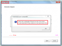
When you first start Hornresp there is a Help tab top far left.
Click on it. Second down is the input wizard.
Click on it.
Choose half space to match normal simulation conditions.
Choose direct radiator.
Choose transmission line
Choose mass loaded
First segment choose Parabolic
Second segment choose parabolic
The input driver parameters are for the standard Hornresp driver. You will have to enter your driver parameters in there.
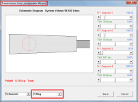
You can modify the stuffing and the section profiles in either the input screen or the Loudspeaker Wizard under tools menu.
This will at least get you started.
The manual will help you more.
Hornresp works with sections that you define the two end area quantities.
- - - - -
This will at least get you started.
The manual will help you more.
Thanks!
I have started the software and made some graphs with a woofer and something that I could like. The figures went crazy, to many reasons. I didn’t figure out (in the ten minutes I used it) how to insert damping. I will certainly read the manual. I just couldn’t see how I could import anything from MathCad.
You won't be able to import anything from mathcad. But looking at your design you can simulate it if you know the dimensions.
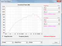
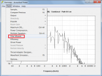
I didn’t figure out (in the ten minutes I used it) how to insert damping.
It is done using the Loudspeaker Wizard - see attachments.
Attachments
Thanks David, and Thanks Mark!
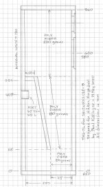
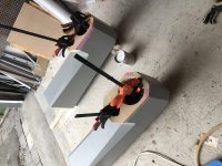
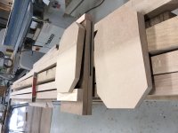
Been doing HiFi projects since I was 8, which was 1964 but only from “just doing what seem reasonable” or from someone else’s design. Last totally new Elsinores (from this DIY site), lately a total remake of Rauna Leira, which inspired me to look at a tapered MLTL design. Paul Kittinger made me this enclosed design. The Leira (or ET as my woofer call it) strange look is a consequence of wanting a chamber with back part of the pipe going all the way up. I wanted a chamber but not the ET look and ended up here. See below pictures
Been doing HiFi projects since I was 8, which was 1964 but only from “just doing what seem reasonable” or from someone else’s design. Last totally new Elsinores (from this DIY site), lately a total remake of Rauna Leira, which inspired me to look at a tapered MLTL design. Paul Kittinger made me this enclosed design. The Leira (or ET as my woofer call it) strange look is a consequence of wanting a chamber with back part of the pipe going all the way up. I wanted a chamber but not the ET look and ended up here. See below pictures
Attachments
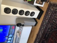
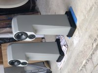
The big Elsinores are really great but biiiiiig. I was thinking of surprise her with a smaller build. The grey ones, ET (as my wife call them) are for our weekdays home (just tested alongside the Elsinores). They are originally made by a legendary speaker designer/producer in the 70s without basically no calculations and computing. Made with a concrete and some polyester mixture. Really dead material. Totally re-modelled with new drivers, xo and damping a few years ago by the guys who bought Mr Hansson’s company. I bought the kit for the speakers and renovated them to modern fairly good standard.Nice speakers!
Attachments
-
 D5BAF6C0-6447-4116-B648-50B636639448.jpg1 MB · Views: 240
 -
 311A4D93-32A1-45EB-B86F-1E15BF94EEF2.jpg1,008.2 KB · Views: 228
 -
 F4FFAD52-CF9C-4DBC-96C2-B8E1414B81EE.jpg752.8 KB · Views: 239
 -
 7DBF62E0-21F2-408D-889E-B1F9A6169634.jpg551.5 KB · Views: 210
 -
 FA499FF7-FD88-4972-BE21-CEF227C34FD7.jpg752.8 KB · Views: 200
 -
 4943A1CF-694C-4FE4-B936-A40404B24A17.jpg1.1 MB · Views: 106
Then I need to get into the xo business. Never done before. Know fairly good the theory but never designed any. Need to find a software that works with the output from HR so I get the box involvements correct.
Luckily I’m am since a month a pensioner...
Luckily I’m am since a month a pensioner...
Need to find a software that works with the output from HR.
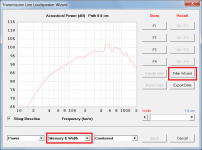
Have you tried using the Hornresp filter wizard?
If a passive rather than an active filter is required, it can only be specified from the main output windows. The effect of absorbent filling material will not be included in that case.
Attachments

I will not use an active filter and multiple amplifiers. Just a traditional 2nd order (probably) filter with coils, resistors and conductors for a xo freq at 2 kHz. As I have both the driver specs and the cabinet design (not yet in Hornresp though) I thought I might as well use the information. Including the use of damping material (which is actually what does a design usable).
The pieces to use:
- Driver specs
- Cabinet design (and output graphs/figures)
- Damping design for the above cabinet (incl output as above)
- Xo designer which manage all the above
- Some good knowledge to put the above to a working xo
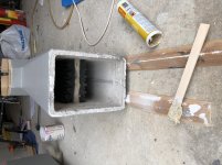
I understand that MathCad and HR work differently. From the above enclosed hand drawing of the cabinet would you say that there are four pipe elements to the design? 1 = Cylindric (the chamber behind the drivers), 2 = tapered cylinder (left pipe downwards), 3 = cylindric (bottom from left to right), 4 = tapered cylinder (right going upwards, with the vent). In that case would you for HR measure the length in the middle of each part?
The pieces to use:
- Driver specs
- Cabinet design (and output graphs/figures)
- Damping design for the above cabinet (incl output as above)
- Xo designer which manage all the above
- Some good knowledge to put the above to a working xo
I understand that MathCad and HR work differently. From the above enclosed hand drawing of the cabinet would you say that there are four pipe elements to the design? 1 = Cylindric (the chamber behind the drivers), 2 = tapered cylinder (left pipe downwards), 3 = cylindric (bottom from left to right), 4 = tapered cylinder (right going upwards, with the vent). In that case would you for HR measure the length in the middle of each part?
I will not use an active filter and multiple amplifiers. Just a traditional 2nd order (probably) filter with coils, resistors and conductors for a xo freq at 2 kHz. As I have both the driver specs and the cabinet design (not yet in Hornresp though) I thought I might as well use the information. Including the use of damping material (which is actually what does a design usable).
The pieces to use:
- Driver specs
- Cabinet design (and output graphs/figures)
- Damping design for the above cabinet (incl output as above)
- Xo designer which manage all the above
- Some good knowledge to put the above to a working xo
I understand that MathCad and HR work differently. From the above enclosed hand drawing of the cabinet would you say that there are four pipe elements to the design? 1 = Cylindric (the chamber behind the drivers), 2 = tapered cylinder (left pipe downwards), 3 = cylindric (bottom from left to right), 4 = tapered cylinder (right going upwards, with the vent). In that case would you for HR measure the length in the middle of each part?
Well you have a chamber behind the driver and a tapered section that you can model as one section easily. Plus your vent. Not to hard to input at all.
Your existing design has simply wrapped the tapered section around a 180 degree bend that you can measure through the centre line and get a pretty close simulation.
Your existing design has simply wrapped the tapered section around a 180 degree bend that you can measure through the centre line and get a pretty close simulation.
My thinking was that the bottom part of the bend is actually not tapered. It has the same square are at the left part against the left “ tapered pipe” as against the right “tapered pipe”. So that’s why I wanted to calculate all different areas as their own parts. Tapered and cylindrical, two of each.
Would this be to overdo it? (Not doing it will go against my “engineering soul”)
You can do exactly as you say. And it will work out well.
Have you tried using the Hornresp filter wizard?
I have a similar question on that. I'd like to calculate the impact of a serial crossover from a 2-way speaker on the HR simulation of the woofer.
I'm interested mostly in the low bass impact, so a passive series coil in th HR filter
might do?
Even if it does, as the filling is not calculated it might not give that much usable information.
Another question: How can i get the "roomgain" calculated? It's greyed out regardless of the frequency-range setting. I guess i need to put in data of the room somewhere?
Hi all,
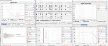
I am now simulating and closing in the design of my first DIY louspeaker ever, a 12"/6.5"/1"+WG design! I' m more excited than my wife, to say the least 🙂
I am here trying to design a TL for the SB34NRXL from SBacoustics, and did a 1:10 scaled drawing, and entered pretty accurate areas and length into HornResp via 4 segment transmission line.
Transmission Line properties:
Length=1m87
Offset=0.21
Tapper=1:8.8
Volume=89L
Driver properties:
Qes (after inductors) =~0.35
Fs(free air)=22Hz
Vas=205L
TL_SB34NRXL_1m87_90L_Offset0.21.PNG
I heard that a TL would be optimized when both impedance peaks are of same height. Not sure why. Is that true?
My design goals are deep and articulate bass, and keep a high sensitivity to avoid as much attenuation as possible on the 6.5" MR16P-4 mid.
I have a hard time knowing if I got a line length too long or if my volume is too large.
I know it depends on design goal, but let me know if you see something off.
Also, I am not too worried about the ripple above 200Hz as the line is a 3-fold (not simulated by HornResp). Shoudl I be more worried? 🙂
Thanks to David McBean and others. I've learned about HornResp just 2days ago and feel it still has a lot more hidden features 🙂. Thanks for sharing this great tool.
Attachments
Last edited:
I'm interested mostly in the low bass impact, so a passive series coil in th HR filter might do?
Even if it does, as the filling is not calculated it might not give that much usable information.
If all you require is a passive series coil, then just add the series inductance value to the driver Le. That way, you can still use the loudspeaker wizard to include filling.
How can i get the "roomgain" calculated?
You can't - at least not in Hornresp. What you can do however, is to import room gain data and have it added to the response calculated by Hornresp. Select menu File > Import > Room Gain Profile from the main input parameters window. For more details search for references to 'room gain' in the Hornresp Help file using the Help file Find tool.
- Home
- Loudspeakers
- Subwoofers
- Hornresp