Hello what are the most accurate models for ltspice. Ayumi or derk reefman, or others in 2020 ?
Thank you.
Thank you.
Good question. I had never heard of the Derk Reefman models until now. I would also like to know where these models can be downloaded.Hello what are the most accurate models for ltspice. Ayumi or derk reefman, or others in 2020 ?
Thank you.
Good question. I had never heard of the Derk Reefman models until now. I would also like to know where these models can be downloaded.
You can download ExtractModel here from uTracer website. You should read the post "paint_kit and extractmodel equations" that the parameter Kg1 between the two is not compatible due to a change of G1 equation in Derk model's Kg1 is 1/2 that of Paint Kit.
Last edited:
Derk's models have appeared in Ale Moglia's posts.
6P15P triode strapped models – Bartola(R) Valves
--
6P15P triode strapped models – Bartola(R) Valves
--
Hello what are the most accurate models for ltspice. Ayumi or derk reefman, or others in 2020 ?
Thank you.
Hi Frederico
One should distinguish between models for vacuum diodes, triodes and tetrodes/pentodes.
For vacuum diodes and triodes, I did a detailed comparison of all important spice approaches two years ago. You will find my essay on my tube-website:
http://adrianimmler.simplesite.com/440956786
My essay will empower you to build your own opinion to that question! 😉
all the best, Adrian
Last edited:
Adrian, it would be great if you would generate a model for the 6SN7, which we all love and hate in equal measure.Hi Frederico
One should distinguish between models for vacuum diodes, triodes and tetrodes/pentodes.
For vacuum diodes and triodes, I did a detailed comparison of all important spice approaches two years ago. You will find my essay on my tube-website:
http://adrianimmler.simplesite.com/440956786
My essay will empower you to build your own opinion to that question! 😉
all the best, Adrian
Adrian, it would be great if you would generate a model for the 6SN7, which we all love and hate in equal measure.
Yes, I will generate one - at the weekend, when I find more time for that.
Raytheon has very good grid current curves in the datasheet, so that will be my basis:
https://tubedata.altanatubes.com.br/sheets/138/6/6SN7WGT.pdf
cheers, Adrian
Fabulous, many thanks. Then we can make a comparison with the other models for this tube. They are very close to each other, but give a suspiciously low THD when used with a CCS in the anode together with a large value for -Vg.Yes, I will generate one - at the weekend, when I find more time for that.
Raytheon has very good grid current curves in the datasheet, so that will be my basis:
https://tubedata.altanatubes.com.br/sheets/138/6/6SN7WGT.pdf
cheers, Adrian
Adrian, it would be great if you would generate a model for the 6SN7, which we all love and hate in equal measure.
...here it is!
As mentioned, its is based on the Raytheon 6SN7WGT data sheet.
While the negative grid voltage range was easy to fit, the positive grid voltage range was difficult. But the result is usable up to Vg=16V.
all the best, Adrian
Code:
*6SN7WGT LTspice model based on the generic triode model from Adrian Immler, version i4
*A version log is at the end of this file
*Params fitted to the datasheet by Adrian Immler, Febr. 2020
*The high fit quality is presented at adrianimmler.simplesite.com
*History's best of tube decribing art (plus some new ideas) is merged to this new approach.
*@ neg. Vg, Ia accuracy is similar to Koren or Ayumi models.
*@ small neg. Vg, the "Anlauf" current is considered.
*@ pos. Vg, Ig and Ia accuracy is on a unrivaled level.
*This offers new simulation possibilities like bias point setting with MOhm grid resistor,
*Audion radio circuits, low voltage amps, guitar distortion stages or pulsed stages.
*                    anode (plate)
*                    | grid
*                    | | cathode
*                    | | |
.subckt 6SN7WGT.RAi4 A G K
.params
*Parameters for the space charge current @ Vg <= 0
+ mu   = 21.3 ;Determines the voltage gain @ constant Ia
+ rad  = 6k2  ;Differential anode resistance, set @ Iad and Vg=0V
+ Vct  = 0.83 ;Offsets the Ia-traces on the Va axis. Electrode material's contact potential
+ kp   = 147  ;Mimics the island effect
+ xs   = 1.5  ;Determines the curve of the Ia traces. Typically between 1.2 and 1.8
*
*Parameters for assigning the space charge current to Ia and Ig @ Vg > 0
+ kB   = 0.14 ;Describes how fast Ia drops to zero when Va approaches zero.
+ radl = 370  ;Differential resistance for the Ia emission limit @ very small Va and Vg > 0
+ tsh  = 10   ;Ia transmission sharpness from 1th to 2nd Ia area. Keep between 3 and 20. Start with 20.
+ xl   = 1.5  ;Exponent for the emission limit
*
*Parameters of the grid-cathode vacuum diode
+ kvdg  = 188 ;virtual vacuumdiode. Causes an Ia reduction @ Ig > 0.
+ kg = 2k15   ;Inverse scaling factor for the Va independent part of Ig (caution - interacts with xg!)
+ Vctg = 0.83 ;Offsets the log Ig-traces on the Vg axis. Electrode material's contact potential
+ xg   = 1.2  ;Determines the curve of the Ig slope versus (positive) Vg and Va >> 0
+ VT   = 0.1  ;Log(Ig) slope @ Vg<0. VT=k/q*Tk (cathodes absolute temp, typically 1150K)
+ Vft2 = 0 gft2 = 7  ;finetunes the gridcurrent @ low Va and Vg near zero
*
*Parameters for the caps
+ cag  = 3p7  ;From datasheet
+ cak  = 0p8  ;From datasheet
+ cgk  = 2p5  ;From datasheet
*
*special purpose parameters
+ os = 1      ;Overall scaling factor, if a user wishes to simulate manufacturing tolerances
*
*Calculated parameters
+ Iad = 100/rad  ;Ia where the anode a.c. resistance is set according to rad.
+ ks = pow(mu/(rad*xs*Iad**(1-1/xs)),-xs) ;Reduces the unwished xs influence to the Ia slope
+ ksnom = pow(mu/(rad*1.5*Iad**(1-1/1.5)),-1.5) ;Sub-equation for calculating Vg0
+ Vg0 = Vct + (Iad*ks)**(1/xs) - (Iad*ksnom)**(2/3) ;Reduces the xs influence to Vct.
+ kl = pow(1/(radl*xl*Ild**(1-1/xl)),-xl) ;Reduces the xl influence to the Ia slope @ small Va
+ Ild = sqrt(radl)*1m ;Current where the Il a.c. resistance is set according to radl.
*
*Space charge current model
Bggi GGi 0 V=v(Gi,K)+Vg0 ;Effective internal grid voltage.
Bahc Ahc 0 V=uramp(v(A,K)) ;Anode voltage, hard cut to zero @ neg. value
Bst   St 0 V=uramp(max(v(GGi)+v(A,K)/(mu), v(A,K)/kp*ln(1+exp(kp*(1/mu+v(GGi)/(1+v(Ahc)))))));Steering volt.
Bs    Ai K I=os/ks*pow(v(St),xs) ;Langmuir-Childs law for the space charge current Is
*
*Anode current limit @ small Va
.func smin(z,y,k) {pow(pow(z+1f, -k)+pow(y+1f, -k), -1/k)} ;Min-function with smooth trans.
Ra  A Ai 1
Bgl Gi A I=min(i(Ra)-smin(1/kl*pow(v(Ahc),xl),i(Ra),tsh),i(Bgvd)*exp(4*v(G,K))) ;Ia emission limit
*
*Grid model
Bvdg G Gi I=1/kvdg*pwrs(v(G,Gi),1.5) ;Reduces the internal effective grid voltage when Ig rises
Rgip G Gi 1G ;avoids some warnings
.func Ivd(Vvd, kvd, xvd, VTvd)  {if(Vvd < 3, 1/kvd*pow(VTvd*xvd*ln(1+exp(Vvd/VTvd/xvd)),xvd), 1/kvd*pow(Vvd, xvd))} ;Vacuum diode function
Bgvd Gi K I=Ivd(v(G,K) + Vctg - uramp(-v(A,K)/mu), kg/os, xg, VT)
.func ft2() {gft2*(1-tanh(3*(v(G,K)+Vft2)))} ;Finetuning-func. improves ig-fit @ Vg near -0.5V, low Va.
Bgr Gi Ai I=ivd(v(GGi),ks/os, xs, 0.8*VT)/(1+ft2()+kB*v(Ahc));Is reflection to grid when Va approaches zero
Bs0 Ai K  I=ivd(v(GGi),ks/os, xs, 0.8*VT)/(1+ft2()) - os/ks*pow(v(GGi),xs) ;Compensates neg Ia @ small Va and Vg near zero
*
*Caps
C1 A G {cag}
C2 A K {cak}
C3 G K {cgk}
.ends
*
*Version log
*i1 :Initial version
*i2 :Pin order changed to the more common order „A G K“ (Thanks to Markus Gyger for his tip)
*i3 :bugfix of the Ivd-function: now also usable for larger Vvd
*i4: Rgi replaced by a virtual vacuum diode (better convergence). ft1 deleted (no longer needed)
;2 new prarams for Ig finetuning @ Va and Vg near zero. New overall skaling factor os for aging etc.
Attachments
Last edited:
That's just great, Adrian - many thanks. I'll get simulating with it straight away, and report back....here it is!
As mentioned, its is based on the Raytheon 6SN7WGT data sheet.
While the negative grid voltage range was easy to fit, the positive grid voltage range was difficult. But the result is usable up to Vg=16V.
all the best, Adrian
...freshly backed for you, rongon! 😀😀
cheers, Adrian
I finally got a chance to check out the 1S4 model and it appears to be working very well. Thanks very much for your efforts!
--
I finally got a chance to check out the 1S4 model and it appears to be working very well. Thanks very much for your efforts!
--
I'm glad to know that! Enjoy it! 🙂
cheers, Adrian
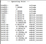
OK, I've done 3 separate simulations for this tube, the Immler, the Duncan and the Ayumi. They all give identical results in every aspect, down to 6 decimal places. Surely this can't be right! I have used the 'long-hand' method, as first taught to me by Admin Mooly. I can only think that I have made an error in my file-naming or writing to the 'tube.lib' file. I need to check, but I have my doubts.That's just great, Adrian - many thanks. I'll get simulating with it straight away, and report back.
OK, I've done 3 separate simulations for this tube, the Immler, the Duncan and the Ayumi. They all give identical results in every aspect, down to 6 decimal places. Surely this can't be right! I have used the 'long-hand' method, as first taught to me by Admin Mooly. I can only think that I have made an error in my file-naming or writing to the 'tube.lib' file. I need to check, but I have my doubts.
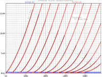
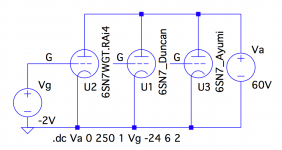
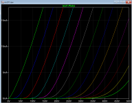
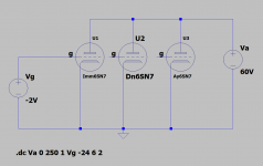
I would recommend to drive a.dc simulation, e.g. like that:
.dc Va 0 250 1 Vg -24 6 2 (see attached picture)
with all the 6SN7 models you have, in parallel connected.
This way, you will easy see the differences of the models.
cheers, Adrian
Attachments
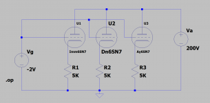
OK, thanks, Adrian. I'll get cracking on it straight away.I would recommend to drive a.dc simulation, e.g. like that:
.dc Va 0 250 1 Vg -24 6 2 (see attached picture)
with all the 6SN7 models you have, in parallel connected.
This way, you will easy see the differences of the models.
cheers, Adrian
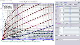
Here is my Raytheon 6sn7 model with grid current level 2, see how it compared with any other model:
Code:
* [URL="http://www.dmitrynizh.com/tubeparams_image.htm"]www.dmitrynizh.com/tubeparams_image.htm[/URL]
* Plate Curves image file: 6sn7-ry.png
* Data source link:
*----------------------------------------------------------------------------------
.SUBCKT 6SN7_RY 1 2 3 ; Plate Grid Cathode
+ PARAMS: CCG=3P  CGP=1.4P CCP=1.9P
+ MU=21 KG1=1287 KP=174.8 KVB=997 VCT=0 EX=1.26
+ VGOFF=5.328 IGA=0.057 IGB=3.339 IGC=15.81 IGEX=0.7954
* Vp_MAX=250 Ip_MAX=87.5 Vg_step=4 Vg_start=20 Vg_count=12
* Rp=4000 Vg_ac=55 P_max=5 Vg_qui=-48 Vp_qui=300
* X_MIN=32 Y_MIN=35 X_SIZE=821 Y_SIZE=576 FSZ_X=1296 FSZ_Y=736 XYGrid=false
* showLoadLine=n showIp=y isDHT=n isPP=n isAsymPP=n showDissipLimit=y
* showIg1=y gridLevel2=y isInputSnapped=n
* XYProjections=n harmonicPlot=n dissipPlot=n
*----------------------------------------------------------------------------------
E1 7 0 VALUE={V(1,3)/KP*LOG(1+EXP(KP*(1/MU+(VCT+V(2,3))/SQRT(KVB+V(1,3)*V(1,3)))))}
RE1 7 0 1G  ; TO AVOID FLOATING NODES
G1 1 3 VALUE={(PWR(V(7),EX)+PWRS(V(7),EX))/KG1}
RCP 1 3 1G   ; TO AVOID FLOATING NODES
C1 2 3 {CCG} ; CATHODE-GRID
C2 2 1 {CGP} ; GRID=PLATE
C3 1 3 {CCP} ; CATHODE-PLATE
RE2 2 0 1G
EGC 8 0 VALUE={V(2,3)-VGOFF} ; POSITIVE GRID THRESHOLD
GG 2 3 VALUE={(IGA+IGB/(IGC+V(1,3)))*(MU/KG1)*(PWR(V(8),IGEX)+PWRS(V(8),IGEX))}
.ENDS
*$
Attachments

Just to be clear, is this the plot you asked me to do?I would recommend to drive a.dc simulation, e.g. like that:
.dc Va 0 250 1 Vg -24 6 2 (see attached picture)
with all the 6SN7 models you have, in parallel connected.
This way, you will easy see the differences of the models.
cheers, Adrian
Attachments
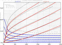
Just to be clear, is this the plot you asked me to do?
Yes, exactly!
Would you be so kind and plot Ia and Ig of all triodes?
Hi KoonwHere is my Raytheon 6sn7 model with grid current level 2, see how it compared with any other model:
Well done!
For negative Vg, there are no significant differences to mine. for positive Vg, your plate current is more accurate while my grid current is more accurate.
Congratulations!
Yes, sure, but in the meantime I have done this one. No difference. Something's wrong!Yes, exactly!
Would you be so kind and plot Ia and Ig of all triodes?
Attachments
- Home
- Amplifiers
- Tubes / Valves
- Vacuum Tube SPICE Models