Hi Pillo69
I meant something else: the point in the MODEL NAME.
So please check if .subckt EL33MUi4p works instead of .subckt EL33.MUi4p
I meant something else: the point in the MODEL NAME.
So please check if .subckt EL33MUi4p works instead of .subckt EL33.MUi4p
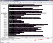
".end" means everything after it will be ignored. ".ends" mean "end of subckt". I always correct for it. 😉Hello Adrian. The "." "end" cannot be removed. I have checked other valves and the expression is ".ends". I have modified with ".ends" and it does not give error. You can see it in the image. I will test its use and comment.
Just tried in MC12 and it runs with no problems. Below is your ECC81_i2 model (with my modifications in the calculated parameters section and changed .end to .ends) and it runs fine with the "." in the name.Hi Pillo69
I meant something else: the point in the MODEL NAME.
So please check if .subckt EL33MUi4p works instead of .subckt EL33.MUi4p
Code:
*
*ECC81 LTspice model based on the generic triode model from Adrian Immler, version i2
*A version log is at the end of this file
*Params fitted to measured values of a Philips sample by Adrian Immler, Oct. 2018
*The high fit quality is presented at adrianimmler.simplesite.com
*History's best of tube decribing art (plus some new ideas) is merged to this new approach.
*@ neg. Vg, Ia accuracy is similar to Koren or Ayumi models.
*@ small neg. Vg, the "Anlauf" current is considered.
*@ pos. Vg, Ig and Ia accuracy is on a unrivaled level.
*This offers new simulation possibilities like bias point setting with MOhm grid resistor,
*Audion radio circuits, low voltage amps, guitar distortion stages or pulsed stages.
*                anode (plate)
*                | grid
*                | | cathode
*                | | |
.subckt ECC81.i2 A G K
+params:
*Parameters for the space charge current @ Vg <= 0
+ mu   = 70 ;Determines the voltage gain @ constant Ia
+ rad  = 10000 ;Differential anode resistance, set @ Iad and Vg=0V
+ Vct  = 0.5 ;Offsets the Ia-traces on the Va axis. Electrode material's contact potential
+ kp   = 173 ;Mimics the island effect
+ xs   = 1.5 ;Determines the curve of the Ia traces. Typically between 1.2 and 1.8
*
*Parameters for assigning the space charge current to Ia and Ig @ Vg > 0
+ kB   = 0.27 ;Describes how fast Ia drops to zero when Va approaches zero.
+ radl = 420 ;Differential resistance for the Ia emission limit @ very small Va and Vg > 0
+ tsh  = 8 ;Ia transmission sharpness from 1th to 2nd Ia area. Keep between 3 and 20. Start with 20.
+ xl   = 1.2 ;Exponent for the emission limit
*
*Parameters of the grid-cathode vacuum diode
+ Rgi  = 80 ;Internal grid resistor. Causes an Ia reduction @ Ig > 0.
+ kg = 500 ;Inverse scaling factor for the Va independent part of Ig (caution - interacts with xg!)
+ Vctg = -0.07 ;Offsets the log Ig-traces on the Vg axis. Electrode material's contact potential
+ xg   = 1.3 ;Determines the curve of the Ig slope versus (positive) Vg and Va >> 0
+ VT   = 0.101 ;Log(Ig) slope @ Vg<0. VT=k/q*Tk (cathodes absolute temp, typically 1150K)
*
*Parameters for the caps
+ cag  = 1p6    ;From data sheet. May lead to gain-decrease @ highest audible frequencies!
+ cak  = 0p2    ;From data sheet
+ cgk  = 2p3    ;From data sheet. "grid to all except anode"
*
*Calculated parameters
+ Iad = {100/rad}  ;Ia where the anode a.c. resistance is set according to rad.
+ ks = {pow(mu/(rad*xs*Iad**(1-1/xs)),-xs)} ;Reduces the unwished xs influence to the Ia slope
+ ksnom = {pow(mu/(rad*1.5*Iad**(1-1/1.5)),-1.5)} ;Sub-equation for calculating Vg0
+ Vg0 = {Vct + (Iad*ks)**(1/xs) - (Iad*ksnom)**(2/3)} ;Reduces the xs influence to Vct.
+ kl = {pow(1/(radl*xl*Ild**(1-1/xl)),-xl)} ;Reduces the xl influence to the Ia slope @ small Va
+ Ild = {sqrt(radl)*1m} ;Current where the Il a.c. resistance is set according to radl.
*
*Space charge current model
Bggi GGi 0 V=v(Gi,K)+Vg0 ;Effective internal grid voltage.
Bahc Ahc 0 V=uramp(v(A,K)) ;Anode voltage, hard cut to zero @ neg. values
Bst   St 0 V=max(v(GGi)+v(Ahc)/(mu), v(Ahc)/kp*ln(1+exp(kp*(1/mu+v(GGi)/(1+v(Ahc))))));Steering volt.
Bs    Ai K I=ft1()/ks*pow(v(St),xs) ;Langmuir-Childs law for the space charge current Is
.func ft1() {1+(1+tanh(4*v(GGi)))/20} ;Finetuning-function for better overall fit at pos Vg
*
*Anode current limit @ small Va
.func smin(z,y,n) {pow(pow(z+1f, -n)+pow(y+1f, -n), -1/n)} ;Min-function with smooth trans.
Ra  A Ai 1
Bgl Gi A I=min(i(Ra)-smin(1/kl*pow(v(Ahc),xl),i(Ra),tsh),i(Bgvd)*exp(4*v(G,K))) ;Ia emission limit
*
*Grid model
Rgi G Gi {Rgi} ;Internal grid resistor for "Ia-reduction" @ Vg > 0
.func Ivd(Vvd, kvd, xvd, VTvd)  {1/kvd*pow(VTvd*xvd*ln(1+exp(Vvd/VTvd/xvd)),xvd)} ;Vacuum diode function
Bgvd Gi K I=Ivd(v(G,K)+Vctg-1m*sqrt(v(Ahc)), kg, xg, VT) ;Grid-cathode vacuum diode
.func ft2() {7*(1-tanh(3*(v(G,K)+Vg0)))} ;Finetuning-func. improves ig-fit @ Vg near -0.5V, low Va.
Bgr Gi Ai I=ft1()*ivd(v(GGi),ks, xs, 0.8*VT)/(1+ft2()+kB*v(Ahc));Is reflection to grid when Va approaches zero
Bs0 Ai K  I=ft1()*ivd(v(GGi),ks, xs, 0.8*VT)/(1+ft2()) - ft1()/ks*pow(v(GGi),xs) ;Compensates neg Ia @ small Va and Vg near zero

*Caps
C1 A G {cag}
C2 A K {cak}
C3 G K {cgk}
.ends
*
*Version log
*i1 :Initial version
*i2 :Pin order changed to the more common order „A G K“ (Thanks to Markus Gyger for his tip)The i3 and i4 models I get a floating point error.
Last edited:
Adrian, maybe you can make the file for EL33 with the model "i2", to use in MC12.?
As indicated by cogsncogs.
As indicated by cogsncogs.
I tried all the available 6n7 and 6n7s triodes models and none of them works right with a current source as the THD is increased by 40db or more than when you're using regular anode resistors, while with the same schematic(electrostatic headphones amplifier-thus C as a load), the 6SN7 model have the same THD content with the same idle current, voltage, load current output and schematic as when resistor loaded.With 6SN7 and same current source i also get les anode voltage by 100v, but the output is the same as with 6n7s, just less distorted by 40...50db..6N7S? They appear to be. Below is a model for the 6N7S in the low current region, below 20mA. Positive grid region is not modeled.
Code:* ============================================================== * 6N7S LTSpice model * Koren model (5 parameters): mean fit error 0.264943mA * Traced by Wayne Clay on 12/26/2019 using Curve Captor v0.9.1 * and Engauge Digitizer 10.4 from Soviet datasheet * ============================================================== .subckt 6N7S P G K Bp P K I=(0.01068292927m)*uramp(V(P,K)*ln(1.0+exp((7.196465919)+ + (7.196465919)*(37.98500662)*V(G,K)/sqrt((0.07628267106k)+ + (V(P,K))**2)))/(7.196465919))**(1.312942692) Cgp G P 2.4p ; 0.0p added (2.4p) Cgk G K 4.3p ; 0.0p added (4.3p) Cpk P K 5.4p ; 0.0p added (5.4p) Rpk P K 1.0G ; to avoid floating nodes d3 G K dx1 .model dx1 d(is=1n rs=2k cjo=1pf N=1.5 tt=1n) .ends 6N7S
Last edited:
Adrian, I have deleted "the dot", I have also replaced it with "an underscore" as I have seen in other designs. When using the tube it gives an error. Look at the photograph.
Pillo69,
you modified the Ild codeline in a wrong way. The bracket "{" should be set AFTER the "=".
You asked if I would do again a EL33 i2 model - sorry, I won't. It would take several hours again to do so, and it is also not sure that it will work in MC, as cogsncogs tested just my i2 triode model (not my i2 pentode model).
@ cogsncogs, thanks for that hint regarding the .ends. I will consider that for future.
kind regards, Adrian
I thank you for your efforts Adrian. I think I've gotten the EL33 tube to work on MC12. This afternoon I will definitely test and comment on the answer.
Adrian, the file works for EL 33 in MC12.
The changes mentioned by cogsncogs in "+" of params and the braces in "Calculated parameters", plus the change made in ".end / .ends" allow it. Thanks for your attention.
The changes mentioned by cogsncogs in "+" of params and the braces in "Calculated parameters", plus the change made in ".end / .ends" allow it. Thanks for your attention.
Sorry to say that "floating point" glitches have appeared, as cogsncogs previously commented.
Hi fewa
You will find a good 6AL5 model in my tube library:
http://adrianimmler.simplesite.com/440956786
BTW, it is the only 6AL5 model which describes the initial velocity current, important if you intent to use the 6AL5 for small signal conditioning. 😀
all the best, Adrian
Thank you!Hi fewa
You will find a good 6AL5 model in my tube library:
http://adrianimmler.simplesite.com/440956786
BTW, it is the only 6AL5 model which describes the initial velocity current, important if you intent to use the 6AL5 for small signal conditioning. 😀
all the best, Adrian
Which software are you using to make tube models?
I cant run curvecaptor on win10
For vacuum diodes, I use Excel (least mean square methode).
But for triodes and pentodes, Excel works not good. I have to fit fully manually. I wish I had a convenient tool!
All the best, Adrian
But for triodes and pentodes, Excel works not good. I have to fit fully manually. I wish I had a convenient tool!
All the best, Adrian
Last edited:
Have you trid Model Paint Tools: Trace Tube Parameters over Plate Curves, Interactively ?
I cant get working model with it.
I cant get working model with it.
Yes, I know this tool well. It is based on Norman Koren's approach, so it delivers good results as long as you are not interested in grid current.
That's why I prefer my own approach, although the model fittig process is not convenient.
all the best, Adrian
That's why I prefer my own approach, although the model fittig process is not convenient.
all the best, Adrian
Code:
* ==============================================================
* 6BC8_Syl LTSpice model
* Koren model (5 parameters): mean fit error 0.36045mA
* Traced by Wayne Clay on 10/21/2014 using Curve Captor v0.9.1
* and Engauge Digitizer from Sylvania datasheet
* ==============================================================
.subckt 6BC8  P G K
    Bp  P K  I=
+ (0.02019891536m)*uramp(V(P,K)*ln(1.0+exp((1.794225622)+
+ (1.794225622)*(54.16463004)*V(G,K)/sqrt((0.9222704089k)+
+ (V(P,K))**2)))/(1.794225622))**(1.439822572)
    Cgp G P 3.7p ; 0.7p added
    Cgk G K 3.9p ; 0.7p added
    Cpk P K 1.8p ; 0.2p added
    Rpk P K 1G ; to avoid floating nodes
    d3  G K dx1
.model dx1 d(is=1n rs=2k cjo=1pf N=1.5 tt=1n)
.ends 6BC8
Code:
*
* Generic triode model: 6BC8
* Copyright 2003--2008 by Ayumi Nakabayashi, All rights reserved.
* Version 3.10, Generated on Fri Feb  3 21:36:55 2017
*               Plate
*               | Grid
*               | | Cathode
*               | | |
.SUBCKT 6BC8_AN A G K
BGG   GG   0 V=V(G,K)+0.058900086
BM1   M1   0 V=(0.070520734*(URAMP(V(A,K))+1e-10))**-5.1932868
BM2   M2   0 V=(0.22410514*(URAMP(V(GG)+URAMP(V(A,K))/11.002365)+1e-10))**6.6932868
BP    P    0 V=0.0057975154*(URAMP(V(GG)+URAMP(V(A,K))/49.094656)+1e-10)**1.5
BIK   IK   0 V=U(V(GG))*V(P)+(1-U(V(GG)))*3.6664566*V(M1)*V(M2)
BIG   IG   0 V=0.0028987577*URAMP(V(G,K))**1.5*(URAMP(V(G,K))/(URAMP(V(A,K))+URAMP(V(G,K)))*1.2+0.4)
BIAK  A    K I=URAMP(V(IK,IG)-URAMP(V(IK,IG)-(0.0030767894*URAMP(V(A,K))**1.5)))+1e-10*V(A,K)
BIGK  G    K I=V(IG)
* CAPS
CGA   G    A 1.4p
CGK   G    K 2.5p
CAK   A    K 1.3p
.ENDSHi FEWA,
do you mean you are trying to build one of the icon of the 60's the Altec 436? Please give an update of your work I am very interested...all the best
do you mean you are trying to build one of the icon of the 60's the Altec 436? Please give an update of your work I am very interested...all the best
- Home
- Amplifiers
- Tubes / Valves
- Vacuum Tube SPICE Models