Yes, I've seen that.
One more curious thing. When I work from the Input Wizard and go to "Schematic" I see the first picture. If I then close the Wizard, change the "Loudspeaker Configuration" to the same, then start the Wizard again, I get the 2nd picture.
One more curious thing. When I work from the Input Wizard and go to "Schematic" I see the first picture. If I then close the Wizard, change the "Loudspeaker Configuration" to the same, then start the Wizard again, I get the 2nd picture.
Attachments

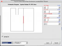
If I then close the Wizard, change the "Loudspeaker Configuration" to the same, then start the Wizard again, I get the 2nd picture.
This is because the driver offset parameters Lo1 and Lo2 are set to zero by default when a BP4, BP6S or BP6P band pass loudspeaker configuration is selected. In your first picture the Lo1 offset value is specified as 9.60 cm, and in your second picture Lo1 has been reset to zero because the BP4 option has been reselected.
(If the old offset values are retained, it can get quite confusing when experimenting with switching between different band pass topologies on the same record).
Last edited:
Would it be possible to update the wavefront simulator to give the time domain response at given microphone pixels? With an impulse as the sound source?
I know it is not a sophisticated simulation but it is still helpful for understanding diffraction and reflections.
I know it is not a sophisticated simulation but it is still helpful for understanding diffraction and reflections.
Would it be possible to update the wavefront simulator to give the time domain response at given microphone pixels? With an impulse as the sound source?
I am guessing this request has something to do with ongoing investigations into the spark calibration of microphones. It's not going to happen 🙂.
https://www.diyaudio.com/forums/equ...rk-calibration-microphones-2.html#post6175586
CHANGE 2
Hornresp now checks stepped segment designs before the loudspeaker wizard opens, and when required, displays a context-sensitive warning message as shown in the Attachment 1 example.
This is an improvement. Thanks David!
Maybe combined with an unstepped version like the simulation you did for me? Each stepped area is replaced with the average of the two areas.
Stay safe,
You too David. Be very careful.
Each stepped area is replaced with the average of the two areas.
Hi Mårten,
I think I would prefer to leave it to the user to decide how best to approximate a given stepped segment design in the loudspeaker wizard. For example, in my simulation I used the average radius to determine the required area, rather than simply using the average area. In other situations it could perhaps be necessary to adjust individual segment lengths while keeping the overall system length the same. It's really a question of "horses for courses" 🙂.
Kind regards,
David
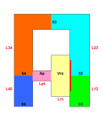
I model this in (TH) as shown. Rear vented chamber and port in yellow and orange shades. This is a constant CSA in both the port and rear chamber portions so no defining ‘port’ or ‘chamber’, just a single closed end pipe. I can shuffle the Vrc/Lrc and Ap/Lpt around and still represent the same exact thing, but through the mid section things get goofy if I split this 50/50 vs 10/90 or 90/10. But the question is what would you fellas use as shown(and adjust for any various driver positions from closed end) or just use a very long Lrc with a minimal Lpt, or? Am I technically suppose to be at the closed end or by chance is the designation of ‘port’ helping describe the driver position at various points in this as L12 is in that section? Thx!
Attachments
Hi Booger weldz,
Hornresp models the rear chamber (Vrc & Lrc) and port (Ap & Lpt) in a tapped horn as shown in Attachment 1. As indicated in the Help file, the port can be omitted if the required inlet area to the horn is equal to Vrc divided by Lrc.
Not sure if this helps to answer your question 🙂.
Stay safe!
David
Attachments
That diagram you made for the tapped horn would be useful for a all the possible variants that Hornresp can make up David. Very easy to understand and get many people over the edge of not knowing what section is doing what. Visiual BASIC have a possible allowance for simple block diagrams in the help file?
Visiual BASIC have a possible allowance for simple block diagrams in the help file?
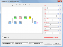
Hi Mark,
The Hornresp Help file is purely text-based. The way that it is set up, it would be difficult to add diagrams of any sort.
What I am currently working on though, as result of the post from 'Booger weldz', is a context-sensitive "acoustic circuit" block diagram for tapped horns in the loudspeaker wizard, similar to those already provided for band pass systems. The tapped horn block diagram will be in the next release, and an example of the sort of thing I have in mind is attached.
In the diagram, H1 to H4 are the horn segments, TC is the throat chamber, D is the driver, RC is the rear chamber and RP is the rear port.
Stay safe!
David
Attachments
Hi Mark,
The Hornresp Help file is purely text-based. The way that it is set up, it would be difficult to add diagrams of any sort.
What I am currently working on though, as result of the post from 'Booger weldz', is a context-sensitive "acoustic circuit" block diagram for tapped horns in the loudspeaker wizard, similar to those already provided for band pass systems. The tapped horn block diagram will be in the next release, and an example of the sort of thing I have in mind is attached.
In the diagram, H1 to H4 are the horn segments, TC is the throat chamber, D is the driver, RC is the rear chamber and RP is the rear port.
Stay safe!
David
OK!
Missed this circuit diagram.
Now that I'm in the asking mode, Multiple entry horns get into this wonderful explanatory mix??
Sometimes explaining this to people without the ability to visualize is a little more than difficult.
Now that I'm in the asking mode, Multiple entry horns get into this wonderful explanatory mix??
I will have a look when I get a chance, but I can't promise anything at this stage. It would require a fair amount of work to implement.
Incidentally, it's good to have you back. When you stopped posting for a while, I was a bit worried that you may have tested positive...
I will have a look when I get a chance
I've had a quick look - a significant amount of work would be required to make it fully context-sensitive, but it would be a neat feature to have 🙂.
Watch this space...
Any design for an 8” tapped horn subwoofer?
Have you tried a Google search for '8" tapped horn subwoofer'?
I will have a look when I get a chance, but I can't promise anything at this stage. It would require a fair amount of work to implement.
Incidentally, it's good to have you back. When you stopped posting for a while, I was a bit worried that you may have tested positive...
I was a bit sick but not from the COVID 19.
I have to make your life a little hard David!
I've had a quick look - a significant amount of work would be required to make it fully context-sensitive, but it would be a neat feature to have 🙂.
Watch this space...
I always watch this space.
😀
I have to make your life a little hard David!
Just what I need - yet more work. You're all heart 🙂.
- Home
- Loudspeakers
- Subwoofers
- Hornresp