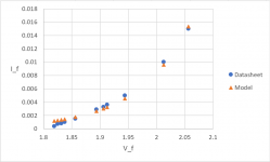
From what I can tell from the datasheet (https://www.mouser.com/datasheet/2/239/LTL-4231N-1139959.pdf), a Spice model for the LTL4231 would look like the following:
.model LTL4231N D (IS=3.55e-12 RS=0.5 N=3.609)
This is based on extracting the I_f/V_f curve from the datasheet using an image and scaling the pixels proportionally to the axes' units.
I_f, V_f
0.0004, 1.81875
0.0007, 1.82500
0.0008, 1.83125
0.0010, 1.83750
0.0015, 1.85625
0.0029, 1.89375
0.0033, 1.90625
0.0036, 1.91250
0.0050, 1.94375
0.0100, 2.01250
0.0150, 2.05625
0.0199, 2.09375
0.0250, 2.13750
0.0300, 2.18125
0.0350, 2.22500
0.0398, 2.26250
0.0450, 2.30625
0.0498, 2.34375
I'm not sure how to accurately get RS, so I just left it as some small value that didn't significantly alter V_f in the 5-15 mA range as compared to the datasheet.
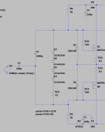
I tossed them into my BA-2 OS model, and I added some small resistance since the voltage reference I need to replace the TL431 is not a neat multiple of the V_f of each (at a reasonable I_f).
Is there a better way to do this?
Critiques are appreciated.
.model LTL4231N D (IS=3.55e-12 RS=0.5 N=3.609)
This is based on extracting the I_f/V_f curve from the datasheet using an image and scaling the pixels proportionally to the axes' units.
I_f, V_f
0.0004, 1.81875
0.0007, 1.82500
0.0008, 1.83125
0.0010, 1.83750
0.0015, 1.85625
0.0029, 1.89375
0.0033, 1.90625
0.0036, 1.91250
0.0050, 1.94375
0.0100, 2.01250
0.0150, 2.05625
0.0199, 2.09375
0.0250, 2.13750
0.0300, 2.18125
0.0350, 2.22500
0.0398, 2.26250
0.0450, 2.30625
0.0498, 2.34375
I'm not sure how to accurately get RS, so I just left it as some small value that didn't significantly alter V_f in the 5-15 mA range as compared to the datasheet.
I tossed them into my BA-2 OS model, and I added some small resistance since the voltage reference I need to replace the TL431 is not a neat multiple of the V_f of each (at a reasonable I_f).
Is there a better way to do this?
Critiques are appreciated.
Attachments
Workout the exact voltage you normally require here.
Then bread board the led arrangement plus a trimpot then work out what current/resistance value you need by turning trimpot.
Replace R5 and R6 with the value you determined experimentally.
That's probably the way I would do it, but there are certainly other ways.
Then bread board the led arrangement plus a trimpot then work out what current/resistance value you need by turning trimpot.
Replace R5 and R6 with the value you determined experimentally.
That's probably the way I would do it, but there are certainly other ways.
Last edited:

Replace R5 and R6 with the value you determined experimentally.
So would you use any resistor where R32 is? R5/R6 appear to control the current, but I’d have to really crank the current >30mA to get enough voltage drop between the gates without R32.
You have around 1.9V to 2V adjustment per led so between 7.6V and 8V for 4 leds (I will look at my curve later for confirmation)
Swap one led for a low voltage zener etc if required.
Putting a high valued trimpot in parallel with the zeners could be used also.
Maybe 100k, then you just lower the value to bleed current away from the leds which will lower the voltage drop across the leds. This is for fine tweaking though, you still want to make sure you have around 3 mA minimum through the leds. Determine what you need for R6 and R5 experimentally first. The trimpot in parallel will assist with lowering the voltage drop but only a small amount.
I think this is what itsme is also suggesting.
There are quite a few ways to finish this puzzle. Don't give up on it.
Make it happen.
Last edited:
Thanks, all. Gotta finish up the Aleph before putting solder to wire on this but I’ll run some sims for swapping a zener or tl431 for the last LED (I think my target is about 8.7-9.0V between the gates).
My thought was that adding a resistor in series would enable me to keep 4 LEDs to maximize the negative temp coefficient effect of the string - I’ll have to ponder why 3 LEDs + zener is preferable to 4 LEDs + resistor. I could probably get away with 4 LEDs and a LM385-1.2. I’m not sure about the “popcorn” noise I saw earlier in the thread - I’ll have to read about that.
My thought was that adding a resistor in series would enable me to keep 4 LEDs to maximize the negative temp coefficient effect of the string - I’ll have to ponder why 3 LEDs + zener is preferable to 4 LEDs + resistor. I could probably get away with 4 LEDs and a LM385-1.2. I’m not sure about the “popcorn” noise I saw earlier in the thread - I’ll have to read about that.

Thanks, all.
I’ll have to ponder why 3 LEDs + zener is preferable to 4 LEDs + resistor. .
Not saying it's better, just giving you other ideas to try.
Use whatever approach that most appeals to you.
...I think this is what itsme is also suggesting...
The resistor string is for adjusting offset voltage at the output.
I fine tuned the bias by trimming the source resistor values.
The TL431 is a great little device, but surprisingly noisy - avoid if possible, have a look with a 'scope 😱
Replace R5 and R6 with the value you determined experimentally.
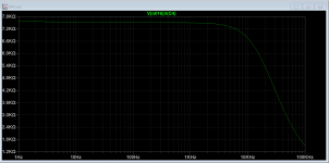
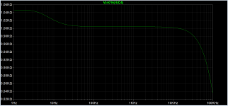
So I'm learning that R5 and R6 have a pretty big effect on the input impedance of the output stage. Pictured first is the input impedance with something similar to the standard TL431 biasing setup for the BA-2/F4, and pictured second is the same measurement when I substitute the LED biasing setup shown here. R5 and R6 are set low in order get get ~10 mA through the LEDs for good regulation; the standard values of R5 and R6 only pull ~1 mA. That might be enough, but I'm not sure what is "good enough" from this chart.
For something like the M2, where the Edcor drives the output stage, this can make a pretty big difference, and may require another buffer after the Edcor.
The tinkering continues . . .
Attachments
Last edited:
Bias Stability
Hi All,
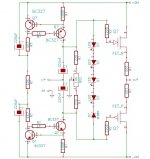
Try biasing complementary O/P stage with a typical hexfet e.g. IRF610, screw it onto one of the o/p mosfets or as close as possible to overcome thermal tracking latency. Then watch stability. Since both have the same thermal drift behaviour that absolutely cancels drift.
Regards
Mehmet
Hi All,
Try biasing complementary O/P stage with a typical hexfet e.g. IRF610, screw it onto one of the o/p mosfets or as close as possible to overcome thermal tracking latency. Then watch stability. Since both have the same thermal drift behaviour that absolutely cancels drift.
Regards
Mehmet
Vbe Multiplier
Absolutely the best solution, though not regarded.
Regards
Mehmet
Vbe multiplier?
Absolutely the best solution, though not regarded.
Regards
Mehmet
Illuminated case like a gaming computer?
Absolute newbie here attempting an F6 build.
I like the idea of a string of blue LED's glued down to the circuit boards to illuminate the case from inside.
If any of you genius (i.e. dumb and dumber) amp builders find a blue LED part that works let me know!!
-Tom-
Absolute newbie here attempting an F6 build.
I like the idea of a string of blue LED's glued down to the circuit boards to illuminate the case from inside.
If any of you genius (i.e. dumb and dumber) amp builders find a blue LED part that works let me know!!
-Tom-
I haven't tried these yet, 2 pico and I were looking at green LEDs. However, these will probably work Ok. You would only need two of them in series to set the bias in an F6.
LTL42UB6N Lite-On | Mouser
I would also suggest using a current regulating diode such as the Semitec E-562 instead of a resistor to set the current through the LEDs. No need to glue the LEDs to the board, just solder them together and insert them in place of the zener diodes. Make sure the LED diodes are pointing in the opposite direction of the zener.
OK I ordered the LTL42UB6N LED's and Semitec E-562's.
1) Definitely use the Semitec E-562 or is this just another option.
2) "Solder them together and insert them in place of the zener diodes. Make sure the LED diodes are pointing in the opposite direction of the zener." In series, right? And I am confused about direction of the zener and LED, how do I tell?
3) I got extra of the LED's. Can I substitute the LTL42UB6N Blue LED for the TLHR6400 Red LED recommended for the DIY PSU board?
Thanks for your help to this poor newb wandering in the wilderness.
-Tom-
Oh here is some "Blue Light Special" music: YouTube
1) Using a current source such as the E-562 will give somewhat more constant current through your LEDs, regardless of noise on the power supply. These also have a slightly negative tempco, which is what we are going for. Having said that, these can be replaced by 3.3k resistors. You will need to identify which end of each resistor location is the positive (+) end. Since the E-562 acts as a diode, the end with the black band is the negative (–) end. They will only work in one direction.
2) The blue LEDs are soldered in series, which will give about 6V total. The two series connected LEDs replace a single zener diode as the voltage reference. Since the zeners are used in their reverse conduction mode, their arrow points 'backwards' to the flow of current, making the tip of the arrow the + terminal and the shaft the – terminal. The long lead of each LED is the + side, so that end will be soldered into the hole for the + terminal of the zener.
3) At the end of the day, an LED is a light source, and may certainly be used to replace any color as you wish.
- Home
- Amplifiers
- Pass Labs
- Dumb Biasing Mod, applicable to F6 and other Papa Amps. Possibly My Dumbest Idea Yet