Even though this one has more adjustments, it requires more brain cells.
This is off the LED topic, but I latched onto this idea due to the increased input impedance (the TLV431 can operate with less than 1 mA passing through it, permitting higher resistance values to the rails than with LEDs). I went through the calculations below as a thought experiment. Hopefully it might be useful to someone.
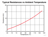
Here's a nice (nearly) linear PTC thermistor: https://www.ti.com/lit/ds/sbos921e/sbos921e.pdf.
Using WebPlotDigitizer to extract the Resistance-Temp data (WebPlotDigitizer - Copyright 2010-2020 Ankit Rohatgi), we get a nice fit with the function Resistance = 8638 * exp(0.00607 * Temp).
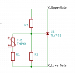
Since it's a PTC thermistor, we can use it to shift the reference of the TLV431 in the following circuit (attached)
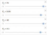
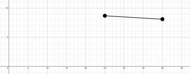
R1 is optional - it just makes the transition more linear, although this particular PTC is already quite linear. I put together an interactive calculator to determine the resistor values R2 and R3: PTC_bias
Alternatively, you could arbitrarily set R3 and fiddle with R1 and R2. Take your pick.
For setup, I imagine starting out with no thermistor and manually controlling the voltage spread. Measure the voltage spread at the desired bias at room temperature, and then measure (and tweak) to find the voltage spread that achieves that same bias at operating temperature. This provides the necessary inputs to find the resistor values to make the thermistor connects the dots.
Attachments
ATL431, not TLV431
Correction to the above: TLV431 has a max cathode-anode voltage of 7 V. Instead of running the TL431 at low shunt currents, perhaps the ATL431 would be better.
Correction to the above: TLV431 has a max cathode-anode voltage of 7 V. Instead of running the TL431 at low shunt currents, perhaps the ATL431 would be better.

Here is much of useful knowledge, Thank you @all
Guys
You've been great a help with this thread.
I got this problem right now to compensate BIAS Idle Current which has to be 500ma and up to 2.8 Amps under full load with a 4 Ohm loudspeakers. (100Watts) or more if there is need for it.
OH BTW it's for a SEPP or the way I call it "Variable Current Source Class A Amplifier", which when Idle uses only about 500MA Current and will increase Current with the strength of Signal..
The SEPP means Single End Push Pull Class A, at least this is the way Nelson Pass calls it..
Output transistors are not the problem these got up to 55Degrees Celsius only but BIAS and signal Drive Transistors getting real hot 80degrees +, even mounted on a large heat sink. Drive Trans are MJE15034, Output MJE 4281 input BC 640 @1 Watt linear 10hz - 214Khz +- 0.2dbin real time.
Now I test some of the advises from here and from other places.
Using WB's way of taking care, helps quite a lot,, I do not want to use a FAN in this amp.
But Rail voltage is 84 Volts without Amp connected and 78.8 with one SIDE OF THAT CLASS A CONNECTED.. Vrail +- 39.5 volts
Sound is just fantastic
The rest you can read in my other thread which is about that amplifier..
It's a bipolar Amp, not mosfet..
BTW the Amp puts out 22Volts RMS into 8 Ohms easy and on 2 Ohms it still puts out 15.6 Volts which is 120 Watts RMS, distortion less than 0.2%
Attachments
Last edited:
Does anyone have any pictures of the LED mod on the board? I think I am understanding everything right.
I have the 3k3 on r7 and r8 as and will be replacing 6v zeners that came with the kit. Should I put anything else in my cart before I do the order? I have 30 LEDs (I plan on doing more amps and they are super cheap). I need to put three in place of each of the 4 zeners (2 per channel) on the amp.
I am also going to replace the mosfets with IRFP150's while I have the amp taken apart.
I know these are dumb questions but I don't want to forget anything.
Also, go from one solder pad to the the three LEDs tied in series to the other solder pad of the zener. If the LEDs don't light up, flip the LED assembly around?
Thanks!
Sounds good so far. I think there might be a picture in this thread somewhere of the LED installation. And there are a couple more F6 threads to look at as well.. Just remember that the LEDs are used as normal diodes, so they will 'point' in the opposite direction of the Zener diode icon on the PCB.
Tungston, I have been looking for pics as I am going through the F6 threads. Thanks!
Another question, are the Keratherm insulators from the DIY store reusable?
Another question, are the Keratherm insulators from the DIY store reusable?
The Keratherm insulators are just barely reusable, if handled with extreme care. I much prefer the Aavid ceramic insulators, both for durability and thermal performance.
Is this the one:
4180G Aavid | Mouser
Also, the store sells the kit with matched 240 mosfets. I thought that it mentioned somewhere that there is no actual need or advantage for matched mosfets in the F6. I suspect that ordering the IRFP150's from Mouser, they should be matched close enough.
If successful, I will publish a few pics and links to the parts that I ordered for future reference.
Yes, that's the insulator I was referring to.
The F6 doesn't really require matched Mosfets. I ordered 20 pieces of FQH44N10 and just pulled them out of the tube four at a time.
The F6 doesn't really require matched Mosfets. I ordered 20 pieces of FQH44N10 and just pulled them out of the tube four at a time.
Thanks. I will go ahead and order the parts. I saw you mentioned that you like running the FQH44N10 at high bias.
Have you thought of starting a TungstenAudio F6 mod thread?
Have you thought of starting a TungstenAudio F6 mod thread?
Finished the mod. Replaced each zener with the LED assembly pictured above. Amp is more detailed, slightly less warm. Treble and mids and bass are tighter and more detailed. I am getting details that I didn't get before.
I like this mod. I also replaced the IRFP240's with IRFP150s at the same time. I used the ceramic insulators above with Arctic silver MX-5 paste. I have to set the bias higher. That may bring some of the relaxed nature of the F6 back. right now I have it at .5v for testing.


google json checker
I like this mod. I also replaced the IRFP240's with IRFP150s at the same time. I used the ceramic insulators above with Arctic silver MX-5 paste. I have to set the bias higher. That may bring some of the relaxed nature of the F6 back. right now I have it at .5v for testing.
google json checker
Last edited:
well, we all know that ZM Is Master of Dumbness
that's probably the reason that I can't imagine from where that sound quality difference is coming, if all is changed is just voltage reference for bias circuit
whatever, I'll continue to happy wallow in my happy ignorance
oh, wait ....... you replaced IRFP type ....... maybe that's the sole reason for change in sound?

I would expect that most of the qualitative difference in sound is coming from the IRFP150 substitution. The green LEDs will allow the amp to reach thermal equilibrium a little faster, due to their negative temperature coefficient; more bias current initially, then decreasing slightly as the amp warms up..
You can also try using a lower value for the gate stopper resistors to open up the top end a little. The 150s have about twice the input capacitance as the 140s. Incidentally, this is why I went with the FQH parts; they have a lower gate capacitance and high transconductance.
Thanks for adding your photos. Enjoy!
Okay. Sounds good I will crank the bias up tonight and play around with it more.
Is there any particular value that you suggest on the gate stopper resistors?
Is there any particular value that you suggest on the gate stopper resistors?
Try something around 47R for the gate stopper resistors.
If you already have 47R in place, try 22R.
If you already have 47R in place, try 22R.
Last edited:
- Home
- Amplifiers
- Pass Labs
- Dumb Biasing Mod, applicable to F6 and other Papa Amps. Possibly My Dumbest Idea Yet