1)
2) The blue LEDs are soldered in series, which will give about 6V total. The two series connected LEDs replace a single zener diode as the voltage reference. Since the zeners are used in their reverse conduction mode, their arrow points 'backwards' to the flow of current, making the tip of the arrow the + terminal and the shaft the – terminal. The long lead of each LED is the + side, so that end will be soldered into the hole for the + terminal of the zener.
3) At the end of the day, an LED is a light source, and may certainly be used to replace any color as you wish.
I am currently using 3x green Leds (LTL4231N) to replace the zener in the F6.
Will the 3Led lit up during operation? Mine didn't, maybe i have connected them the wrong way round?
My bad, had them installed the wrong way.
Rectified and now powered up, cooking @ 1.7A on bench, no sound test yet.
Rail voltage on SLB is +/- 25.9Vdc.
Heatsink temp ramped up pretty fast, and stabilized at 55 'ish degC.
Thanks TA
Rectified and now powered up, cooking @ 1.7A on bench, no sound test yet.
Rail voltage on SLB is +/- 25.9Vdc.
Heatsink temp ramped up pretty fast, and stabilized at 55 'ish degC.
Thanks TA
Those red-orange LEDs will probably be Ok. The voltage will be good with three LEDs in series and a 3.3k resistor.
The temperature coefficient will be a little different than the green LEDs, but it will still be negative, which is what we want.
The temperature coefficient will be a little different than the green LEDs, but it will still be negative, which is what we want.
Those red-orange LEDs will probably be Ok. The voltage will be good with three LEDs in series and a 3.3k resistor.
The temperature coefficient will be a little different than the green LEDs, but it will still be negative, which is what we want.
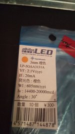
Thank you for reply. There was a lot of LED at Akihabara.
I choiced for warmer color...
My bad, had them installed the wrong way.
Rectified and now powered up, cooking @ 1.7A on bench, no sound test yet.
Rail voltage on SLB is +/- 25.9Vdc.
Heatsink temp ramped up pretty fast, and stabilized at 55 'ish degC.
Thanks TA
Good Job
F4 Biasing Mods
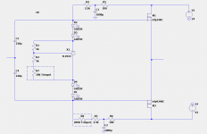
I thought I would do 2 more that could be used on F4 type circuit. This is the first dumb one. The second one is less dumb (I had to use my 2.5 brain cells), I will show that one later.
In this circuit we use a TLV431 device which has a 1.24V reference which will allow us to use 4 Green leds as well as some adjustment.
The regular TL431 won't allow us to use 4 leds with the voltage adjustment we might like to have cause it has a 2.5V reference.
I haven't tested it yet, but it will perform in a similar manner to the F6 circuit.
I hope to test this tomorrow.
Attachments
Last edited:
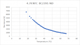
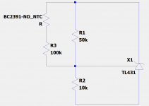
Less Dumb F4 Biasing Circuit
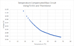
Using it like this (see circuit) gives this Voltage vs Temperature curve (using the data from the measured Resistance Curve above)
Even though this one has more adjustments, it requires more brain cells. I like using less brain cells, and I like LEDs cause you know if it is operating, so I am kind of "biased" toward the LED one above.
Pun not initially intended, but I will go with the flow.
Attachments
Last edited:

Yeah.
I much prefer LEDs.
I have one more that is slightly dumber than the first one.
I much prefer LEDs.
I have one more that is slightly dumber than the first one.
Last edited:
I am happy with my LED modded F6. (14 Leds inside)
It heats up the room, lit up the room and it sings beautifully!
It heats up the room, lit up the room and it sings beautifully!
Not sure how I got hooked on this thread, because I only understand about half of it. But it is still very enjoyable to read. I think it has something to do with a recent aquiring more than a life time supply of diodes, lots of zeners, and tons of LEDs giving me hope that I'll be able to do something with. I also enjoy all the dumb references from so many non "dummies"

- Home
- Amplifiers
- Pass Labs
- Dumb Biasing Mod, applicable to F6 and other Papa Amps. Possibly My Dumbest Idea Yet