Up to .630 on the bias. Temps are in check and the amp sounds great.
Do you think the IRFP150 is prone to oscillation? 6L6 suggests 110ohms which is what I used when building the amp. I don't have a function generator so I am not sure can test for oscillation issues if I started lowering the gate resistor.
Do you think the IRFP150 is prone to oscillation? 6L6 suggests 110ohms which is what I used when building the amp. I don't have a function generator so I am not sure can test for oscillation issues if I started lowering the gate resistor.
The original F6 was built with the now unobtainium SemiSouth power JFets. It was later adapted to use IRFP240 Mosfets. Since then, there have been a number of variations and modifications, as we DIYers like to do. Since you have chosen to work with the IRFP150 devices, you may be blazing your own trail to some extent. The bias current is just one knob that you can use to adjust the sound of your amp. I like to joke a little, saying to crank the bias until the amp starts to melt, then back off a little. The bias current affects the operating point of the device. As long as the heatsinks can be touched for at least a few seconds, and don't pose a danger to dog noses (if present), then you can go to town.
It sounds like you have found a configuration that you like. Now may be a good time to let the amp run in for a while and see how the sound develops over the next 20 to 50 hours or so. Then there are a couple other tweaks that might be fun to try. Maybe 68 Ohm gate stopper resistors instead of 47 Ohms. Maybe different Source degeneration resistors on the lower Q2 devices. Maybe even slightly different bias currents between the upper and lower devices. 2 Pico and I were experimenting with some of these some time ago. The intent was to deliberately introduce a small amount of 2nd harmonic distortion.
I originally found the F6 to be extremely clean sounding, but appreciated a small amount of color from trying different source resistor combos. 2 Pico went so far as to use different types of Mosfets for the Q1 and Q2 locations. So DIY is for fun.
Here is an article that I found to be very instructive regarding the F6:
Attachments
Last edited:
different Iq between upper and lower mosfet ........... means difference is going through your speaker .........

^ Correct, and I wouldn't have suggested that until recently. Yes, Papa's BAF 2021 video discusses this tweak.
Perhaps best left to Fearless Amp Builders.

Perhaps best left to Fearless Amp Builders.
well
do not do that with amplifier
Papa's first tweak - preserving output DC offset where it needs to be
Papa's second tweak - having everything with speaker, nothing with amp itself
do not do that with amplifier
Papa's first tweak - preserving output DC offset where it needs to be
Papa's second tweak - having everything with speaker, nothing with amp itself
I love my F6. It is my favorite amp that I have had by a long shot. I intend to build a second chassis out with either another F6 or a different amplifier board.
I have slowly been going through that writeup that you attached (Thank you!). I saw Mr Pass was talking about the idea of adding a 10 ohm trimmer pot to 0.1uf source resistors to play with the distortion characteristics. Like how you're saying in regards to playing with the values of the source resistors. It would be cool to have a selector on the front with different arrangements of resistance. Maybe like a 3-way selector. forward, euphonic, and hidden sauce.
I thought of doing a few little things like using heatsinks as washers for Q1 and Q2. Maybe attaching heatsinks to the inside of the chassis with thermal paste to the other heatsinks using the UMS holes. Just little ways to get more of the heat out.
Interesting on the different bias current. Is the DC offset essentially a bias adjustment for Q1? Pico's idea of different mosfets for Q1 and Q2 sound interesting as well. I will have to look to see if he wrote about all of that.
I thought of doing a few little things like using heatsinks as washers for Q1 and Q2. Maybe attaching heatsinks to the inside of the chassis with thermal paste to the other heatsinks using the UMS holes. Just little ways to get more of the heat out. I have a digital oscilloscope (Hantek DSO5072P). I am hoping I can measure for parasitic oscillation and 2nd/3rd order harmonics on it. Then I can make progress playing with the source resistors and the gate stopper resistors and not do it blindly. It seems that the oscillation happens at startup as the caps are charging.
The interesting thing about the F6 is how the two bias current adjustments work together. One may be labeled ‘offset’ and the other ‘bias’, but they both do the same thing. When the current through Q1 is equal to the current through Q2, then the offset is zero, and the DC current through your speaker is also zero. Mismatched current between Q1 and Q2 causes a non-zero DC offset.
Your scope will be a good tool to find any oscillation caused by parasitic effects.
Your scope will be a good tool to find any oscillation caused by parasitic effects.
Hi James,
In your explorations about different output transistors, degeneration, etc did you look at the possibility of using the jfet + power fet combination Lu1014 + IRFP240) as used on the F3 amp as a substitute for the 'R100 (SemiSouth SJEP 120100) of the original design?
In your explorations about different output transistors, degeneration, etc did you look at the possibility of using the jfet + power fet combination Lu1014 + IRFP240) as used on the F3 amp as a substitute for the 'R100 (SemiSouth SJEP 120100) of the original design?
That idea actually has occurred to me as well. I haven’t tried it yet. I do have some of the LD1014 surface mount parts and special heat spreaders for them. It’s an intriguing idea that may be tricky to build.
My take on modifying the F6 was using higher rail voltage and the high transconductance FQH44N10. It turned out well.
My take on modifying the F6 was using higher rail voltage and the high transconductance FQH44N10. It turned out well.
I've got those 44H10's ready to change in with a version of Salas' L-Adapter power supply (still looking at +/- 24V) but still having problems with the Aikido gain stage (+8dB) replacing the jfet input buffer - I also ran into problems adapting Mark Johnson's IPS7 pcb and this needs an overall different sub-board + main F6 board layout - a bit slow (a lot!)...
The 250R Rhopoint Manganin resistors as 'gate stoppers' are a bit high so might need to go shopping again - running 2 in // at present! (and they aren't gettin' any cheaper!)
I never did get the F3 to work in my system but it's an intriguing idea to maybe use those little jfets ...
Thanks for the link on yesterday's #102 - well worth re-reading.
I have a plethora of excessively dumb ideas to work through. And not just for the F6.
We could use a version of the F6 that supports interchangeable buffers in front of the Jensen transformer. Sort of like the M2x.
We could use a version of the F6 that supports interchangeable buffers in front of the Jensen transformer. Sort of like the M2x.
Thanks James and 'pico', (Comrade Dan is still tightening the screws, eh!)
I just had a thought about the possibility/feasibility of designing a conversion board so the 4 pins common on all Mark's M2X input boards to match up to the diyA long pcb F6 circuit and this would enable any of the optional M2x input stages to then plugin to the 'standard' diyA F6 pcbs - duh! (should have thought about that before ...)
I have a rather different layout for both the IPS7 (includes a gain option) and for the F6 amp but this won't be compatible with the long diyA boards but a simple adapter/header board would be a rather neat little item, and maybe also to the diyA shop.
Yes to that ^ IPS7 with gain and others. Needs a ground connection to do it properly. Then you also get to use Yara preamp compatible cards.
I want to try something simple with the HV opamp OPA551 and one or two others.
I want to try something simple with the HV opamp OPA551 and one or two others.
Two things:
We need to remember that the IPS7 design uses the unity gain feature in conjunction with the input signal tracking feature on the power supply to apply a constant current load to the output. This won''t work if the opamp is configured to provide gain. One would need to remove the resistor that is connected to the opamp output pin. The rest of the circuit would be Ok after that.
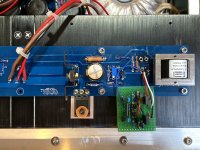
Here is a picture of how I replaced the JFet buffer with an Austin-inspired Diamond buffer. It is somewhat of a tricky build, but it worked well enough. With the current PCB layout, the only way to tap into the necessary electrical connections is at the holes left by removing the JFets.
We need to remember that the IPS7 design uses the unity gain feature in conjunction with the input signal tracking feature on the power supply to apply a constant current load to the output. This won''t work if the opamp is configured to provide gain. One would need to remove the resistor that is connected to the opamp output pin. The rest of the circuit would be Ok after that.
Here is a picture of how I replaced the JFet buffer with an Austin-inspired Diamond buffer. It is somewhat of a tricky build, but it worked well enough. With the current PCB layout, the only way to tap into the necessary electrical connections is at the holes left by removing the JFets.
Attachments
This whole LED thing would be a really nice addition to peufeu's method:
Power amp OUTPUT STAGE measurements shootout
An LED soldered directly to the source pin could give enough "thermal feedback" to omit the source resistors completely I think.
Power amp OUTPUT STAGE measurements shootout
An LED soldered directly to the source pin could give enough "thermal feedback" to omit the source resistors completely I think.
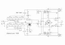
James, that's nicely done especially using the different colours to avoid mistakes - the vero-board layout is as seen previously? Playing around with the gain option and using the 0v point at Z1, now changed to the 3 leds.
Neat little heatsink on the R1, and presumably R2 - what resistors are they?
I ended up using the PBH ones from Isab.h with clipon heatsinks - they're exorbitant price these days ...
Neat little heatsink on the R1, and presumably R2 - what resistors are they?
I ended up using the PBH ones from Isab.h with clipon heatsinks - they're exorbitant price these days ...
Yes, I showed that same vero-board ealier. Just repeating it here for any newcomers.
The resistors at R1 and R2 are 30W thick film 0.4 Ohm, 1%. I wanted precision values at the source resistors to get more repeatable results. Especially since I was experimenting with splitting the resistance above and below the junction with the big capacitor.
The resistors at R1 and R2 are 30W thick film 0.4 Ohm, 1%. I wanted precision values at the source resistors to get more repeatable results. Especially since I was experimenting with splitting the resistance above and below the junction with the big capacitor.
- Home
- Amplifiers
- Pass Labs
- Dumb Biasing Mod, applicable to F6 and other Papa Amps. Possibly My Dumbest Idea Yet