Can someone share the last modified working pcb and schematic of the 100W Ultimate Fidelity Amplifier please
Now if someone could possibly share the latest working pcb layout for this amplifier, I would greatly appreciate it. This is gonna be my next build to power my Onkyo speakers.
Just the latest working pcb layout and the schematic.
Everytime I go through this build thread, and I think I found the right pcb layout, someone suggests something else wrong or that needs to change 🙂
Just the latest working pcb layout and the schematic.
Everytime I go through this build thread, and I think I found the right pcb layout, someone suggests something else wrong or that needs to change 🙂
The layout I used was pretty similar to the original so if there is something better I don't know what it is.
Attachments
Last edited:
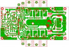
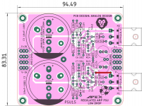
PSU 10R AND PSU 15 , done deal!..😀
Same mounting hole distances maintained. Also given pads for output devices PSU10R, if anyone wants to run wires to heatsink.
regards
prasi
Same mounting hole distances maintained. Also given pads for output devices PSU10R, if anyone wants to run wires to heatsink.
regards
prasi
Attachments

Last edited:
The layout I used was pretty similar to the original so if there is something better I don't know what it is.
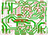
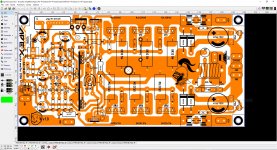
This is the one I had my eye on yes. Thank you sir. Now to try and cut away all the green color and then convert it to black and white.
If anybody has the plain pcb image for the above file shared by still4given, please will you share it.
Thank you
This is the one I had my eye on yes. Thank you sir. Now to try and cut away all the green color and then convert it to black and white.
If anybody has the plain pcb image for the above file shared by still4given, please will you share it.
Thank you
I have it. What is it that your need? Are you going to etch your own boards? If so, do you use toner transfer or Photo sense? I can give you the files for the foil and the silk for the top in PDF.
Hi there
I do the toner transfer method. Sheew, I would really appreciate it if you can offer the black and white pcb images, and silk in pdf and maybe the bom. Its a pain in the behind to try and get rid of all that green in some of the images 🙂
I do the toner transfer method. Sheew, I would really appreciate it if you can offer the black and white pcb images, and silk in pdf and maybe the bom. Its a pain in the behind to try and get rid of all that green in some of the images 🙂
Hi there
I do the toner transfer method. Sheew, I would really appreciate it if you can offer the black and white pcb images, and silk in pdf and maybe the bom. Its a pain in the behind to try and get rid of all that green in some of the images 🙂
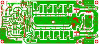
Here is both for those who may also need them.
Attachments
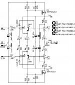
I forgot about the AX-14 Golosa. Not sure about the schematic. I believe Juan Vargas made this layout.
yes Terry I made the layout the schematic is just the AX-14 with extra pairs and a bit of slewmaster to it on the output 🙂
Attachments
Thank you very much guys. It is much appreciated. This gives me something to do while we are on lockdown.
Have a blessed evening further all. Its time to go to bed, its raining cats and dogs in Cape Town South Africa. Cozy stuff
Have a blessed evening further all. Its time to go to bed, its raining cats and dogs in Cape Town South Africa. Cozy stuff
Which is best for subwoofer, AX11TEF or AX14, I imagine the difference between both is irisory, but which would be a good choice?
Hello dear sir
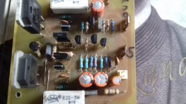
I have assembled this ampl.my both BC 639 and BC 640 emitter resistance 47ohm burn with the supply of 18..0..18 v av @1.5A . Sorry for create hindrance .Thank you
Hello Masood I think a transistor near output transistor in wrong position. Please check you print file and as Gannaji said use dim bulb tester.
Hello dear sir
I have assembled this ampl.my both BC 639 and BC 640 emitter resistance 47ohm burn with the supply of 18..0..18 v av @1.5A . Sorry for create hindrance .Thank you
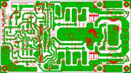
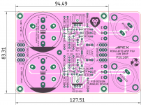
Did you use this pcb?
Attachments


Did you use this pcb?
Dear sir
Thanks to reply.i used this pcb.i usually use series bulb to test.mpsa13 is not available so that i used BC517 whose pin direction is reverse .thank you.
Dear sir
Thanks to reply.i used this pcb.i usually use series bulb to test.mpsa13 is not available so that i used BC517 whose pin direction is reverse .thank you.
Is there 18R instead 180R on your pcb?
- Home
- Amplifiers
- Solid State
- 100W Ultimate Fidelity Amplifier