First cap indeed gets noticeably hotter. Maybe 35 to 40C tops. Second one has less demand for ripple current rating.
Thanks, X.
I would remove R3, R5 and R4, R6 so the capacitors will split the ripple current equally.
That turns a 'CRC' PS into a 'C' PS, does it not?
I thought there were sonic improvements to be had by using a 'CRC' PS rather than a 'C' PS?
And better still - a 'CRCRC' PS?
I like 105 Celsius caps in my power supplies.
Yes, good idea but the ripple-handing capacity of the 105 deg caps is 4.8a - vs. 6.6a for the 85 deg caps.
So, X, can you tell us what actual affect is there on the resulting ripple of the SLB, by lowering ripple-handling capability from 6.6a to 4.8a?
You show the final ripple is ~1mV (with the specified 6.6a caps) ... what would this likely increase to, using 4.8a caps in the first-C position?
If it doubled to, say, 2mV ... is this hearable, in terms of the SQ of the amp?
Andy
The ripple current rating doesn't change sonics - just affects cap lifetime because it doesn't operate as warm/hot. The output ripple voltage is function of CRC values. Bigger C and R will reduce voltage ripple but has high current ripple. The current ripple is function of ESR at 120Hz, low ESR is not what you want for a CRC bulk cap.
I am building the BA-3 Complementary amp next and am debating between one or two SLB's for dual mono. I have read a few posts on here that suggest with the SLB, going true dual mono isn't really necessary, a single transformer with one SLB is sufficient sound quality wise and power wise. What are your official thoughts? What about cross-talk through the PS? Is it lower in the SLB vs the DIY PS120 from the store?
Soundwavesteve,
Is this the BA-3 preamp? I looked at the schematics quickly and it seems to be only needing 45mA bias current. Certainly a single SLB would be more than enough as it’s made for 5000mA (LOL). If you want more channel separation, put a separate CRC between each BA-3 and the SLB. Maybe 2200uF/4.7R/2200uF should really keep any crosstalk well below audible levels. But really, the SLB is way too big for a preamp. Have you considered a smaller preamp sized dual rail cap Mx PSU from Prasi?
Juma's Easy-Peasy Capacitance Multiplier
I use these on my smaller preamps and headphone amps and it works well.
The best PSU for a preamp IMO, is the one that comes with the Yarra preamp.
Those are sold out though. I am working with JPS64 to make a standalone PSU similar to it but with ultra low noise voltage regulators - like TPS7A4XXX. Good for 1amp up to +/-34v.
Last edited:
I am building the full BA-3 power amp with the complementary outputs. So it's the BA-3 input stage and BA-2 output stage together, probably running 32v and as high of a bias as the heatsinks allow. I am building the BA3 preamp separately and am using Tubecad/Glassware's bipolar 24v power supply for that.
I am building the full BA-3 power amp with the complementary outputs. So it's the BA-3 input stage and BA-2 output stage together, probably running 32v and as high of a bias as the heatsinks allow. I am building the BA3 preamp separately and am using Tubecad/Glassware's bipolar 24v power supply for that.
If poweramp at high bias current then SLB is ideal. If you need less than 5A combined from both channels the get 1. If more, than go dual monoblock with two SLBs and two trafos.
Hi Folks,
It’s been brought to my attention that some of the pads on the SLB near the PE NTC and capacitor seem to be contaminated or something - so solder is having a hard time wetting the pads. Please let me know if you run into similar issues. Note that this board is thick 2mm and has thick 2oz copper solid pours. It needs a big iron and a big chisel tip to fully melt the solder.
Thanks,
X
Hi Folks,
It’s been brought to my attention that some of the pads on the SLB near the PE NTC and capacitor seem to be contaminated or something - so solder is having a hard time wetting the pads. Please let me know if you run into similar issues. Note that this board is thick 2mm and has thick 2oz copper solid pours. It needs a big iron and a big chisel tip to fully melt the solder.
Thanks,
X
Interesting. In those specific areas I had to solder on both sides of my board to make sure everything flowed well.
Best,
Anand.
Hi Folks,
It’s been brought to my attention that some of the pads on the SLB near the PE NTC and capacitor seem to be contaminated or something - so solder is having a hard time wetting the pads.
Thanks,
X
Sorry, X - in terms of the dual rail SLB (PCB image attached), where is the "PE NTC and capacitor" located?
Andy
Attachments
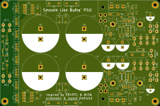
TH1 and C23 - near the protective earth (PE) or Chassis Return spade connector toward right middle.
TH1 and C23 - near the protective earth (PE) or Chassis Return spade connector toward right middle.
Got it - thanks, X! 🙂
Andy
Heatsinks
I have the mondo big sinks and I can use them, but you said they really aren't needed somewhere in these pages. How hot do the get with the smaller ones? Can we use the snap-on or should we stick with the screw on?
I'm speaking of Q9-Q11 on SLB
I have the mondo big sinks and I can use them, but you said they really aren't needed somewhere in these pages. How hot do the get with the smaller ones? Can we use the snap-on or should we stick with the screw on?
I'm speaking of Q9-Q11 on SLB
Attachments
I use those little serrated stamped alum ones with screws - not even warm. If I recall, the dissipation is about 400mW, so not very much.
You can see what they look like in this photo:
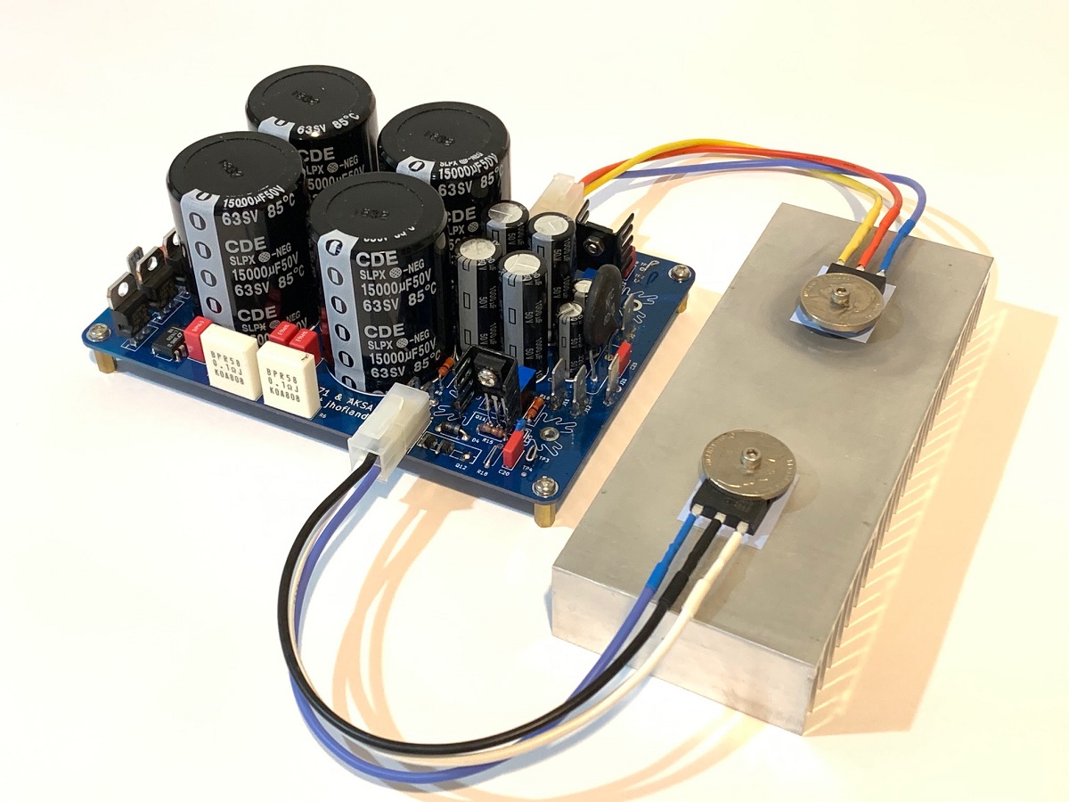
You can see what they look like in this photo:
I was thinking those big honking things where a bit of overkill. I have some little slip-on ones I think will work fine. I'll just monitor them, if they are getting too hot I can always go bigger. Frankly, I don't think it will be an issue as this is a dual mono, so the load isn't going to be incredibly heavy either.
Thanks X
Thanks X
The pinouts for J6 & J14 don't make sense to me.
After some testing with the ohmeter:
Looking into J6 (female on the PCB)
Pin 1 or 3 can go to the base of 2SC5200
Pin 2 goes to the collector
Pin 3 goes to emitter
Then the same is true for 2SA1943?
Actually ignoring the J6 J14 schematic and looking at the print, it makes sense, but looking at those with pins to J17-18-19-20 etc, is just confusing as hell for us newbs lol
JT
JT
Last edited:
This is tricky and the best way to do it is to use an ohmeter between the pads for where the pins would go if they were PCB mounted in the underhung position, and check the Molex jack for continuity. Note that two of the pins are parallel (redundant). If you look at my photo above, you will get a sense of what I am talking about. Even if you followed the schematic, the final double check by eye needs to be done with an ohmeter just like I describe above.
This is tricky and the best way to do it is to use an ohmeter between the pads for where the pins would go if they were PCB mounted in the underhung position, and check the Molex jack for continuity. Note that two of the pins are parallel (redundant). If you look at my photo above, you will get a sense of what I am talking about. Even if you followed the schematic, the final double check by eye needs to be done with an ohmeter just like I describe above.
That's what I did to figure it out my friend.

- Home
- Group Buys
- The SLB (Smooth Like Butter) Active Rect/CRC/Cap Mx Class A Power Supply GB